Nissan Sentra Service Manual: P0197, P0198 EOTSensor
DTC Logic
DTC DETECTION LOGIC
| DTC No. | CONSULT screen terms (Trouble diagnosis content) | DTC detecting condition | Possible cause |
| P0197 | EOT SEN/CIRC (Engine oil temperature sensor circuit low) | An excessively low voltage from the engine oil temperature sensor is sent to ECM. |
|
| P0198 | EOT SEN/CIRC (Engine oil temperature sensor circuit high) | An excessively high voltage from the engine oil temperature sensor is sent to ECM. |
DTC CONFIRMATION PROCEDURE
1.PRECONDITIONING
If DTC Confirmation Procedure has been previously conducted, always perform the following procedure before conducting the next test.
- Turn ignition switch OFF and wait at least 10 seconds.
- Turn ignition switch ON.
- Turn ignition switch OFF and wait at least 10 seconds.
>> GO TO 2.
2.PERFORM DTC CONFIRMATION PROCEDURE
- Start engine and wait at least 5 seconds.
- Check 1st trip DTC.
Is 1st trip DTC detected? YES >> Proceed to EC-264, "Diagnosis Procedure".
NO >> INSPECTION END
Diagnosis Procedure
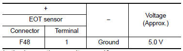
1.CHECK ENGINE OIL TEMPERATURE SENSOR POWER SUPPLY
- Turn ignition switch OFF
- Disconnect engine oil temperature (EOT) sensor harness connector.
- Turn ignition switch ON.
- Check the voltage between EOT sensor harness connector and ground.
Is the inspection result normal? YES >> GO TO 3.
NO >> GO TO 2.
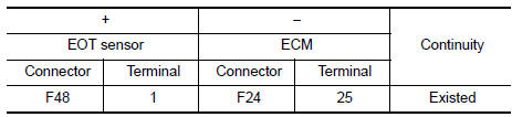
2.CHECK ENGINE OIL TEMPERATURE SENSOR POWER SUPPLY CIRCUIT
- Turn ignition switch OFF.
- Disconnect ECM harness connector
- Check the continuity between EOT sensor harness connector and ECM harness connector.
- Also check harness for short to ground.
Is the inspection result normal? YES >> Perform the trouble diagnosis for power supply circuit.
NO >> Repair or replace error-detected parts.
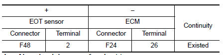
3.CHECK EOT SENSOR GROUND CIRCUIT
- Turn ignition switch OFF.
- Disconnect ECM harness connector.
- Check the continuity between EOT sensor harness connector and ECM harness connector.
- Also check harness for short to power.
Is the inspection result normal? YES >> GO TO 4.
NO >> Repair or replace error-detected parts.
4.CHECK ENGINE OIL TEMPERATURE SENSOR
Check the engine oil temperature sensor. Refer to EC-265, "Component Inspection (EOT Sensor)".
Is the inspection result normal? YES >> Check intermittent incident. Refer to GI-39, "Intermittent Incident".
NO >> Replace engine oil temperature sensor. Refer to EM-94, "Exploded View".
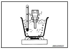
Component Inspection (EOT Sensor)
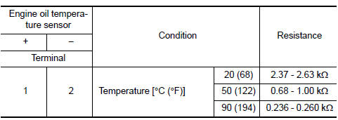
1.CHECK ENGINE OIL TEMPERATURE SENSOR
- Turn ignition switch OFF.
- Disconnect engine oil temperature sensor harness connector
- Remove engine oil temperature sensor.
- Check resistance between engine oil temperature sensor terminals by heating with hot water as shown in the figure.
Is the inspection result normal? YES >> INSPECTION END
NO >> Replace engine oil temperature sensor. Refer to EM-94, "Exploded View".
 P0196 EOT Sensor
DTC Logic
DTC DETECTION LOGIC
NOTE:
If DTC P0196 is displayed with DTC P0197 or P0198, first perform the
trouble diagnosis for DTC P0197 or
P0198. Refer to EC-264, "DTC Logic".
...
 P0222, P0223 TP Sensor
DTC Logic
DTC DETECTION LOGIC
NOTE:
If DTC P0222 or P0223 is displayed with DTC P0643, first perform the
trouble diagnosis for DTC P0643.
Refer to EC-353, "DTC Logic".
DTC No ...
Other materials:
Drive belt
Automatic tensioner
Generator
Water pump
Air conditioner compressor
Crankshaft pully
WARNINGBe sure the ignition switch is in the OFF
or
LOCK position before servicing drive belt.
The engine could rotate unexpectedly.
Visually inspect the belt for signs of ...
Component parts
Moonroof
Moonroof : component parts location
Bcm
(view under instrument panel, left side of
vehicle)
Moonroof switch
Moonroof motor assembly (view with
headliner removed)
Front door lock assembly lh (key cylinder
switch)
Front door switch lh (rh
similar)
Combination met ...
P0181 FTT Sensor
DTC Logic
DTC DETECTION LOGIC
DTC No.
CONSULT screen terms
(Trouble diagnosis content)
DTC detecting condition
Possible cause
P0181
FTT SENSOR
(Fuel temperature sensor ″A″
circuit range/performance)
A)
Rationally incorrect voltage from the
...
