Nissan Sentra B18 (2020-2025) Service Manual: P0011 Ivt Control
Dtc Description
DTC Description
DTC DETECTION LOGIC
|
DTC |
CONSULT screen terms (Trouble diagnosis content) |
DTC detection condition |
|
|
P0011 |
INT/V TIM CONT-B1 (“A� Camshaft position - timing over-advanced or system performance bank 1) |
Diagnosis condition |
— |
|
Signal (terminal) |
Camshaft position sensor signal |
||
|
Threshold |
During the advanced control of intake valve timing control, the angle difference between actual angle and target angle is 13 degrees or more |
||
|
Diagnosis delay time |
6 seconds or more |
||
POSSIBLE CAUSE
-
Crankshaft position sensor
-
Camshaft position sensor
-
Intake valve timing control solenoid valve
-
Accumulation of debris to the signal plate of the camshaft
-
Timing chain installation
-
Foreign matter caught in the oil groove for intake valve timing control
FAIL-SAFE
Engine Control System
|
Engine operating condition in fail-safe mode |
||
|---|---|---|
|
Fail safe mode |
Nissan Sentra Vehicle behavior |
|
|
Device fix mode |
|
|
|
Others |
ECM stops the electric valve timing control. (The camshaft returns to the position of most retard angle.) |
|
Idle Start/Stop System
When a DTC is detected, the start/stop indicator lamp blinks slowly and the idle start/stop system operation is prohibited.
When ECM detects error while operating the idle start/stop system, ECM restarts the engine.
Confirmation Procedure
Confirmation Procedure
-
PRECONDITIONING
If DTC Confirmation Procedure has been previously conducted, always perform the following procedure before conducting the next test.
-
Turn ignition switch OFF and wait at least 10 seconds.
-
Turn ignition switch ON.
-
Turn ignition switch OFF and wait at least 10 seconds.
TESTING CONDITION:
Before performing the following procedure, confirm that battery voltage is between 10 V and 16 V at idle.
>>GO TO 2.
-
-
PERFORM DTC CONFIRMATION PROCEDURE-1
 With CONSULT
-
Turn ignition switch ON and select “DATA MONITOR� mode of “ENGINE� using CONSULT.
-
Start engine and warm it up to normal operating temperature.
-
Maintain the following conditions for at least 13 consecutive seconds. Hold the accelerator pedal as steady as possible.
ENG SPEED
1,200 – 2,000 rpm
COOLANT TEMP/S
More than 60°C (140°F)
Selector lever
P or N position
-
Stop Nissan Sentra vehicle with engine running and let engine idle for 13 seconds.
-
Check 1st trip DTC.
 With GST
Follow the procedure “With CONSULT� above.
Is 1st trip DTC detected?
YES >>Refer to DTC Diagnosis Procedure.
NO >>GO TO 3.
-
-
PERFORM DTC CONFIRMATION PROCEDURE-2
With CONSULT-
Maintain the following conditions for at least 20 consecutive seconds.
ENG SPEED
1,200 – 3,175 rpm (A constant rotation is maintained.)
COOLANT TEMP/S
More than 60°C (140°F)
Selector lever
D position
Driving location
Driving Nissan Sentra vehicle uphill
(Increased engine load will help maintain the driving conditions required for this test.)
CAUTION:
Always drive at a safe speed.
-
Check 1st trip DTC.
With GSTFollow the procedure “With CONSULT� above.
Is 1st trip DTC detected?
YES >>Refer to DTC Diagnosis Procedure.
NO-1 >>To check malfunction symptom before repair: Refer to Intermittent Incident.
NO-2 >>Confirmation after repair: INSPECTION END
-
Dtc Diagnosis Procedure
DTC Diagnosis Procedure
MALFUNCTION A
CAUTION:
Never reuse O-ring of electric intake valve timing control actuator. When replacing the electric intake valve timing control actuator, replace the O-ring.
-
CHECK ELECTRIC INTAKE VALVE TIMING CONTROL MOTOR CONTROL CIRCUIT
-
Turn ignition switch OFF.
-
Disconnect electric intake valve timing control motor harness connector.
-
Disconnect electric intake valve timing control module harness connector.
-
Check the continuity between the electric intake valve timing control motor harness connector and the electric intake valve timing control module harness connector.
Electric intake valve timing control motor
Electric intake valve timing control module
Continuity
Connector
Terminal
Connector
Terminal
F89
1
F80
46
Existed
2
44
-
Also check harness for short to ground and short to power.
Is the inspection result normal?
YES >>GO TO 2.
NO >>Repair or replace error-detected parts.
-
-
CHECK ELECTRIC INTAKE VALVE TIMING CONTROL ACTUATOR BRUSH
-
Remove electric intake valve timing control actuator. Refer to Exploded View.
-
Check the state of brush for the electric intake valve timing control actuator.
Is the inspection result normal?
YES >>GO TO 3.
NO >>Replace the electric intake valve timing control actuator. Refer to Exploded View.
-
-
CHECK ELECTRIC INTAKE VALVE TIMING CONTROL ACTUATOR
-
Check the continuity between electric intake valve timing control actuator connector terminal and brush as following.
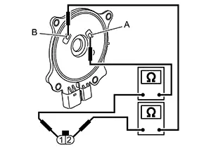
Electric intake valve timing control actuator
Continuity
Terminal
Brush
1
A
Existed
B
Not existed
2
B
Existed
A
Not existed
Is the inspection result normal?
YES >>GO TO 4.
NO >>Replace the electric intake valve timing control actuator. Refer to Exploded View.
-
-
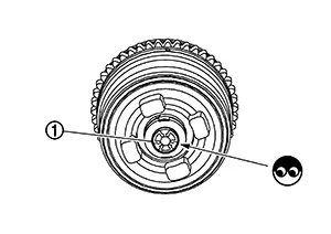
CHECK CENTER TARGET
Check the state of center target
 .
.
Is the inspection result normal?
YES >>Replace camshaft sprocket (INT) (Electric intake valve timing motor is built-in). Refer to Exploded View.
NO >>Repair or replace the center target. Refer to Exploded View.
MALFUNCTION B
-
CHECK TIMING CHAIN INSTALLATION
Check service records for any recent repairs that may cause timing chain misalignment.
Are there any service records that may cause timing chain misalignment?
YES >>Check timing chain installation.Refer to Inspection.
NO >>GO TO 2.
-
CHECK CAMSHAFT SPROCKET AND TIMING CHAIN
Check the following.
-
Visually check for chipping camshaft
sprocket gear tooth.
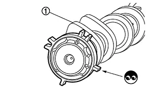
-
Timing chain tension and elongation.
Is the inspection result normal?
YES >>INSPECTION END
NO >>Repair or replace error-detected parts.
-
Other materials:
Dtc Diagnosis [8ch Can Gateway (8ch Can Gateway)]
B2600-42 Config Error
Dtc Description
DTC Description
DTC DETECTION LOGIC
DTC No.
CONSULT screen terms
(Trouble diagnosis
content)
DTC detected
...
B20d2-11 Parking Lamp Pwr Sply Circ
Dtc Description
DTC Description
DTC DETECTION LOGIC
DTC No.
CONSULT screen items
(Trouble diagnosis content)
DTC detection condition
...
Main Line Between Abs and M&a Circuit
Diagnosis Procedure
Diagnosis Procedure
CHECK CONNECTOR
Turn the ignition switch OFF.
Disconnect the battery cable from the
negative terminal.
Check the following terminals and
...