Nissan Sentra Service Manual: Overdrive control switch
Component Function Check
1.CHECK SPORT INDICATOR LAMP FUNCTION
Check OD OFF indicator lamp turns ON for approx. 2 seconds when ignition switch turns ON.
Is the inspection result normal? YES >> GO TO 2.
NO >> Go to TM-239, "Diagnosis Procedure".
2.CHECK SPORT MODE SWITCH FUNCTION
- Shift the selector lever to “D” position.
- Check that OD OFF indicator lamp turns ON/OFF when overdrive control switch is operated.
Is the inspection result normal? YES >> INSPECTION END
NO >> Go to TM-236, "Diagnosis Procedure".
Diagnosis Procedure
1.CHECK OVERDRIVE CONTROL SWITCH CIRCUIT
- Turn ignition switch OFF
- Disconnect CVT shift selector connector.
- Turn ignition switch ON.
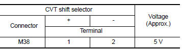
- Check voltage between CVT shift selector harness connector terminals.
 Is the inspection
result normal?
YES >> GO TO 2.
NO >> GO TO 4.
2.CHECK CVT SHIFT SELECTOR ASSEMBLY
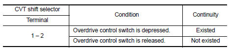
Check continuity between CVT shift selector connector terminals.
 Is the inspection
result normal?
YES >> Check intermittent incident. Refer to GI-39, "Intermittent Incident".
NO >> GO TO 3.
3.CHECK OVERDRIVE CONTROL SWITCH
Check overdrive control switch. Refer to TM-237, "Component Inspection (Overdrive Control Switch)".
Is the inspection result normal? YES >> Replace CVT shift selector assembly. Refer to TM-253, "Removal and Installation".
NO >> Repair or replace malfunctioning parts.
4.CHECK GROUND CIRCUIT
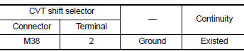
Check continuity between CVT shift selector harness connector terminal and ground.
 Is the inspection
result normal?
YES >> GO TO 5.
NO >> Repair or replace malfunctioning parts.
5.CHECK CIRCUIT BETWEEN COMBINATION METER AND CVT SHIFT SELECTOR (PART 1)
- Turn ignition switch OFF
- Disconnect combination meter connector.
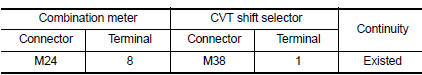
- Check continuity between combination meter harness connector terminal and CVT shift selector harness connector terminal.
 Is the inspection
result normal?
YES >> GO TO 6.
NO >> Repair or replace malfunctioning parts.
6.CHECK CIRCUIT BETWEEN COMBINATION METER AND CVT SHIFT SELECTOR (PART 2)
Check continuity between combination meter harness connector terminal and ground.
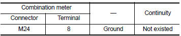 Is the inspection
result normal?
YES >> GO TO 7.
NO >> Repair or replace malfunctioning parts.
7.CHECK COMBINATION METER INPUT SIGNAL
- Connect all of disconnected connectors.
- Turn ignition switch ON.
- Select “Data Monitor” in “METER/M&A”.
- Select “O/D OFF SW”.
- Check that “O/D OFF SW” turns ON/OFF when overdrive control switch is operated. Refer to MWI-20, "Reference Value".
Is the inspection result normal? YES >> Check intermittent incident. Refer to GI-39, "Intermittent Incident".
NO >> Replace combination meter. Refer to MWI-77, "Removal and Installation".
Component Inspection (Overdrive Control Switch)
1.Check overdrive control switch
Check continuity between wires of selector lever knob 1.
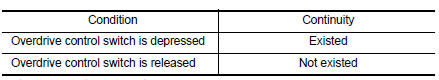 Is the inspection
result normal?
YES >> INSPECTION END
NO >> Replace selector lever knob. Refer to TM-253, "Removal and Installation".
 Main power supply and ground circuit
Diagnosis Procedure
1.CHECK TCM POWER CIRCUIT (PART 1)
Turn ignition switch OFF.
Disconnect TCM connector.
Check voltage between TCM harness connector terminals and ground.
Is the insp ...
 Od off indicator lamp
Component Function Check
1.CHECK OD OFF INDICATOR LAMP FUNCTION
Check OD OFF indicator lamp turns ON for approx. 2 seconds when ignition
switch turns ON.
Is the inspection result normal?
YES ...
Other materials:
1110, C1170 ABS Actuator and electric unit (control unit)
DTC Logic
DTC DETECTION LOGIC
DTC
Display item
Malfunction detected condition
Possible cause
C1110
CONTROLLER FAILURE
When there is an internal malfunction in the ABS actuator
and electric unit (control unit).
ABS actuator and electric unit
(contr ...
AM radio reception
AM signals, because of their low frequency, can
bend around objects and skip along the ground.
In addition, the signals can be bounced off the
ionosphere and bent back to earth. Because of
these characteristics, AM signals are also subject
to interference as they travel from transmitter
to r ...
The oil pressure warning lamp does not turn off
Description
The oil pressure warning lamp remains illuminated while the engine is running
(normal oil pressure).
Diagnosis procedure
1.Check combination meter input signal
Start the engine and select METER/M&A on CONSULT.
Observe oil w/l data monitor and the operation of the oil pres ...
