Nissan Sentra Service Manual: Main power supply and ground circuit
Diagnosis Procedure
1.CHECK TCM POWER CIRCUIT (PART 1)
- Turn ignition switch OFF.
- Disconnect TCM connector.
- Check voltage between TCM harness connector terminals and ground.
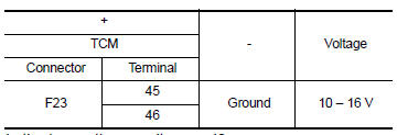
Is the inspection result normal? YES >> GO TO 2.
NO >> GO TO 4.
2.CHECK TCM POWER CIRCUIT (PART 2)
Check voltage between TCM harness connector terminals and ground.
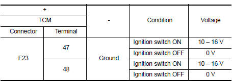
Is the inspection result normal? YES >> GO TO 3.
NO >> GO TO 5.
3.CHECK TCM GROUND CIRCUIT
Check continuity between TCM harness connector terminals and ground.
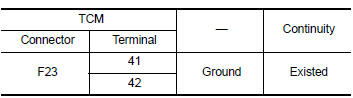 Is the inspection
result normal?
YES >> Check intermittent incident. Refer to GI-39, "Intermittent Incident".
NO >> Repair or replace malfunctioning parts.
4.DETECT MALFUNCTION ITEMS (PART 1)
Check the following items:
- Open or short circuit of harness between battery positive terminal and
TCM connector terminals 45 and 46.
Refer to PG-8, "Wiring Diagram — Battery Power Supply —".
- 10A fuse (No.33, fuse and fusible link block). Refer to PG-48, "Terminal Arrangement".
- 10A fuse (No.36, fuse and fusible link block). Refer to PG-48, "Terminal Arrangement".
Is the inspection result normal? YES >> Check intermittent incident. Refer to GI-39, "Intermittent Incident".
NO >> Repair or replace malfunctioning parts.
5.DETECT MALFUNCTIONING ITEMS (PART 2)
Check the following items:
- Harness open circuit or short circuit between ignition switch and IPDM E/R. Refer to PG-20, "Wiring Diagram — Ignition Power Supply —".
- Harness open circuit or short circuit between IPDM E/R and TCM.
- 10A fuse (No.45, IPDM E/R). Refer to PG-48, "Terminal Arrangement".
- IPDM E/R
Is the check result normal? YES >> Check intermittent incident. Refer to GI-39, "Intermittent Incident".
NO >> Repair or replace malfunctioning parts.
 P285A Clutch B Pressure
DTC Logic
DTC DETECTION LOGIC
DTC
CONSULT screen terms
(Trouble diagnosis content)
DTC detection condition
Possible causes
P285A
CLUTCH B PRESSURE
(Clutch B Pressur ...
 Overdrive control switch
Component Function Check
1.CHECK SPORT INDICATOR LAMP FUNCTION
Check OD OFF indicator lamp turns ON for approx. 2 seconds when ignition
switch turns ON.
Is the inspection result normal?
YES &g ...
Other materials:
Removal and installation
SIDE OIL SEAL
Removal and Installation
REMOVAL
Remove front drive shafts. Refer to FAX-18, "6M/T : Removal and
Installation (LH)".
Remove differential side oil seals (1) from clutch housing and
transaxle case using a suitable tool.
CAUTION:
Do not damage transaxle case an ...
Diagnosis and repair work flow
Work flow
OVERALL SEQUENCE
DETAILED FLOW
1.INTERVIEW THE CUSTOMER FOR THE SYMPTOM
Interview the customer for the symptom (the condition and the environment
when the incident/malfunction
occurs).
>> GO TO 2.
2.CHECK SYMPTOM
Check the symptom from the customer information.
> ...
Door lock actuator
Driver side
Driver side : component function check
1.CHECK FUNCTION
Select DOOR LOCK of BCM using CONSULT.
Select DOOR LOCK in ACTIVE TEST mode.
Touch ALL LOCK or ALL UNLK to check that it works normally.
Is the inspection result normal?
YES >> Door lock actuator is OK.
NO > ...
