Nissan Sentra Service Manual: Main line between ipdm-e and dlc circuit
Diagnosis procedure
1.Check connector
- Turn the ignition switch OFF.
- Disconnect the battery cable from the negative terminal.
- Check the following terminals and connectors for damage, bend and loose connection (connector side and harness side).
- Harness connector E4
- Harness connector M2
Is the inspection result normal? Yes >> go to 2.
No >> repair the terminal and connector.
2.Check harness continuity (open circuit)
- Disconnect the following harness connectors.
- Ipdm e/r
- Harness connectors e4 and m2
- Check the continuity between the ipdm e/r harness connector and the harness connector.
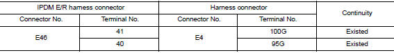
Is the inspection result normal? Yes >> go to 3.
No >> repair the main line between the ipdm e/r and the harness connector e4.
3.Check harness continuity (open circuit)
Check the continuity between the harness connector and the data link connector.
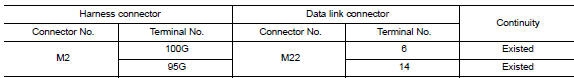
Is the inspection result normal? Yes (present error)>>check can system type decision again.
Yes (past error)>>error was detected in the main line between the ipdm e/r and the data link connector.
No >> repair the main line between the harness connector m2 and the data link connector.
 Can system (type 1)
Dtc/circuit diagnosis ...
 Ecm branch line circuit
Diagnosis procedure
1.Check connector
Turn the ignition switch off.
Disconnect the battery cable from the negative terminal.
Check the terminals and connectors of the ecm for damage, bend and ...
Other materials:
ECU diagnosis information
Diagnosis sensor unit
DTC Index
DIAGNOSTIC CODE CHART
NOTE:
Follow the procedures in numerical order when repairing malfunctioning
parts. Confirm whether malfunction is
eliminated using air bag warning lamp or CONSULT each time repair is finished.
If malfunction is still
observed, proceed ...
Preparation
Special Service Tools
NOTE:
The actual shapes of Kent-Moore tools may differ from those of special
service tools illustrated here.
Commercial Service Tools
...
Precaution
Precaution for supplemental restraint system (srs) "air bag" and "seat belt
pre-tensioner"
The Supplemental Restraint System such as “AIR BAG” and “SEAT BELT
PRE-TENSIONER”, used along
with a front seat belt, helps to reduce the risk or severity of injur ...
