Nissan Sentra Service Manual: ECU diagnosis information
Diagnosis sensor unit
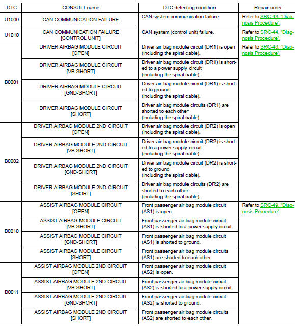
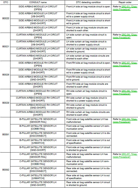
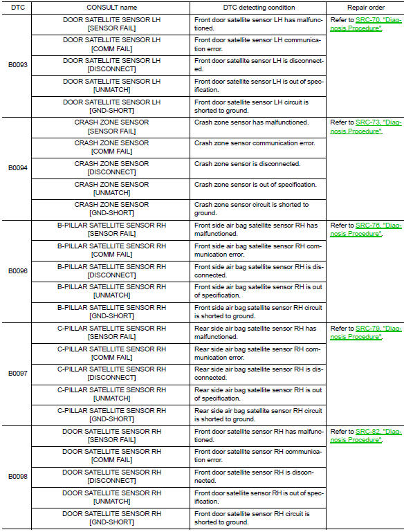
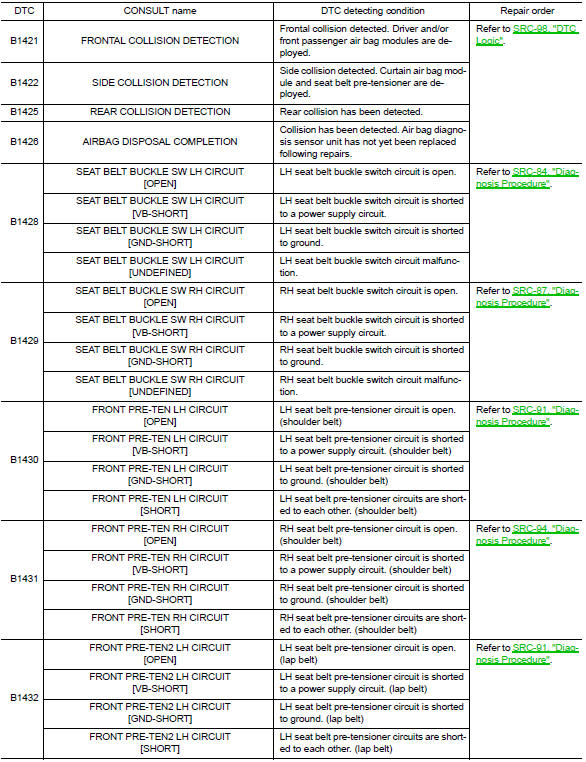
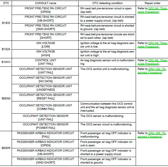
DTC Index
DIAGNOSTIC CODE CHART
NOTE:
Follow the procedures in numerical order when repairing malfunctioning parts. Confirm whether malfunction is eliminated using air bag warning lamp or CONSULT each time repair is finished. If malfunction is still observed, proceed to the next step. When malfunction is eliminated, further repair work is not required.
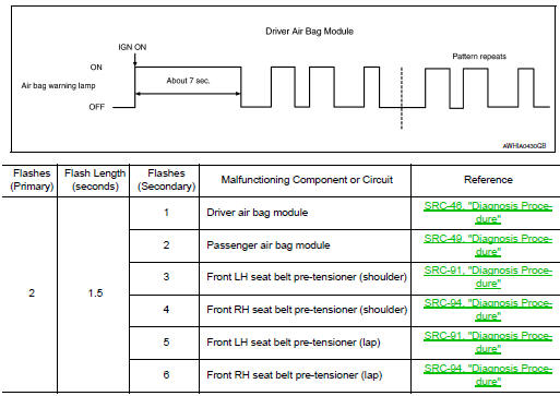
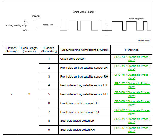
Flash Code Index
WARNING LAMP FLASH CODE CHART
How to read flash codes
- Put the vehicle in Diagnosis Mode. Refer to SRC-17, "Trouble Diagnosis without CONSULT".
- All codes are proceded by a seven second ”holding” flash.
- Identify how many primary flashes are displayed as well as the length of each primary flash.
- Refer to the tables and examples below to determine which SRS subsystem the code belongs to.
- Count the short secondary flashes that follow the primary flashes.
- Match the correct flashing pattern to the malfunctioning component and perform the Diagnosis Procedure.
Refer to the illustrations below for an example of each flashing pattern.
Front subsystem
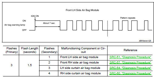
Side subsystem
Air bag subsystem
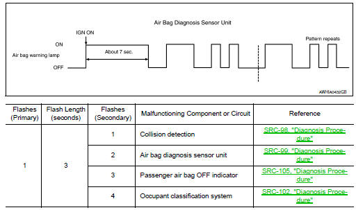
Sensor subsystem
 Diagnosis system (AIR BAG)
Description
CAUTION:
Never use electrical test equipment on any circuit related to the
SRS unless instructed in this Service
Manual. SRS wiring harnesses can be identified by yellow and/or o ...
 Wiring diagram
SRS AIR BAG SYSTEM
Wiring Diagram
...
Other materials:
General maintenance
During the normal day-to-day operation of the
vehicle, general maintenance should be performed
regularly as prescribed in this section. If
you detect any unusual sounds, vibrations or
smells, be sure to check for the cause or have a
NISSAN dealer do it promptly. In addition, you
should notify ...
B0096 Front side air bag satellite sensor RH
Description
DTC B0096 FRONT SATELLITE SENSOR RH
The front side air bag satellite sensor RH is wired to the air bag diagnosis
sensor unit. The air bag diagnosis
sensor unit will monitor the front side air bag satellite sensor RH for internal
failures and its circuits for communication
errors ...
Ecu diagnosis information
Ipdm e/r (intelligent power distribution module engine room)
Reference Value
Values on the diagnosis tool
Terminal layout
Physical values
Fail-safe
Can communication control
When CAN communication with ECM and BCM is impossible, IPDM E/R performs
fail-safe ...
