Nissan Sentra B18 (2020-2025) Service Manual: Interior Lighting System :: Dtc/circuit Diagnosis
Interior Room Lamp Battery Saver Output Circuit. Diagnosis Procedure
Diagnosis Procedure
-
CHECK SYMPTOM
-
Check symptom (A or B).
A
All the following lamps do not turn ON:
-
Front room/map lamp assembly lamp
-
Rear personal lamp
-
Trunk room lamp
-
Vanity mirror lamp LH
-
Vanity mirror lamp RH
B
Interior room lamp battery saver does not activate.
-
Which symptom is detected?
A>>GO TO 2.
B>>GO TO 6.
-
-
CHECK FUSE
-
-
Ignition switch OFF.
-
Check that the following fuses are not blown (open):
Location
Fuse No.
Capacity
Fuse block (J/B)
19
10 A
36
10 A
-
Are the fuses blown (open)?
YES>>Replace the blown fuse after repairing the affected circuit.
NO>>GO TO 3.
-
-
CHECK ROOM LAMP RELAY CIRCUIT 1
-
-
Disconnect room lamp relay connector.
-
Check voltage between room lamp relay harness connector and ground.
+
-
Voltage
(Approx.)
Room lamp relay
Connector
Terminal
J-2
2
Ground
Battery voltage
3
-
Is the inspection result normal?
YES>>GO TO 4.
NO>>Repair or replace harnesses.
-
-
CHECK ROOM LAMP RELAY 1
-
Check room lamp relay. Refer to Component Inspection.
Is the inspection result normal?
YES>>GO TO 5.
NO>>Replace room lamp relay.
-
-
CHECK ROOM LAMP RELAY CIRCUIT 2
-
-
Disconnect BCM connector.
-
Check continuity between room lamp relay harness connector and BCM harness connector.
Room lamp relay
BCM
Continuity
Connector
Terminal
Connector
Terminal
J-2
1
M84
37
Yes
-
Is the inspection result normal?
YES>>Replace BCM. Refer to Removal and Installation.
NO>>Repair or replace harnesses.
-
-
CHECK ROOM LAMP RELAY 2
Check room lamp relay. Refer to Component Inspection.
Is the inspection result normal?
YES>>GO TO 7.
NO>>Replace room lamp relay.
-
CHECK ROOM LAMP RELAY CIRCUIT 4
-
-
Disconnect BCM connector M84.
-
Check continuity between room lamp relay harness connector and ground.
Room lamp relay
—
Continuity
Connector
Terminal
J-2
1
Ground
No
-
Is the inspection result normal?
YES>>Replace BCM. Refer to Removal and Installation.
NO>>Repair or replace harnesses.
-
Component Inspection
Component Inspection
-
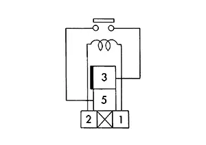
CHECK ROOM LAMP RELAY
-
-
Ignition switch OFF.
-
Disconnect room lamp relay connector.
-
Check continuity between room lamp relay terminals.
Room lamp relay
Condition
Continuity
Terminals
3
5
12 V direct current supply between terminals 1 and 2.
Yes
No current supply
No
-
Is the inspection result normal?
YES >>Inspection End.
NO >>Replace room lamp relay.
-
Interior Room Lamp Power Supply Circuit. Component Function Check
Component Function Check
Note:
Before performing the diagnosis, check that the following items are normal:
-
Interior room lamp battery saver output circuit
-
CHECK INTERIOR ROOM LAMP CONTROL FUNCTION
-
 CONSULT
-
Ignition switch ON.
-
Select “INT LAMP� in "Active Test" mode of "BCM(INT LAMP)".
-
With operating the test items, check that each interior room lamp turns ON/OFF.
On
: Interior room lamp ON
Off
: Interior room lamp OFF
-
Does the interior room lamp turns ON/OFF?
YES >>Interior room lamp power supply circuit is normal.
NO >>Refer to Diagnosis Procedure.
-
Diagnosis Procedure
Diagnosis Procedure
-
CHECK INTERIOR ROOM LAMP POWER SUPPLY CIRCUIT
-
-
Ignition switch OFF.
-
Disconnect the following connectors:
-
Room lamp relay connector.
-
Front room/map lamp assembly
-
Rear personal lamp
-
Trunk room lamp
-
Vanity mirror lamp LH
-
Vanity mirror lamp RH
-
-
Check continuity between room lamp relay harness connector and each interior room lamp harness connector.
Room lamp relay
Interior room lamp
Continuity
Connector
Terminal
Connector
Terminal
J-2
5
Front room/map lamp assembly
R3
8
Yes
Rear personal lamp
R103
1
Trunk room lamp
B78
1
Vanity mirror lamp LH
R104
2
Vanity mirror lamp RH
R105
-
Check continuity between room lamp relay harness connector and ground.
Room lamp relay
—
Continuity
Connector
Terminal
J-2
5
Ground
No
-
Is the inspection result normal?
YES >>GO TO 2.
NO >>Repair or replace harnesses.
-
-
CHECK INTERIOR ROOM LAMP GROUND CIRCUIT
-
Check continuity between each interior room lamp harness connector and ground.
Interior room lamp
—
Continuity
Connector
Terminal
Front room/map lamp assembly
R3
7
Ground
Yes
Rear personal lamp
R103
2
Is the inspection result normal?
YES>>Refer to Intermittent Incident.
NO>>Repair or replace harnesses.
-
Interior Room Lamp Control Circuit. Component Function Check
Component Function Check
Note:
Before performing the diagnosis, check that the following items are normal:
-
Interior room lamp power supply circuit
-
Front room/map lamp assembly bulb
-
Rear personal lamp bulb
-
CHECK INTERIOR ROOM LAMP CONTROL FUNCTION
-
CONSULT
-
Switch the map lamp switch and room lamp switch to DOOR position.
-
Ignition switch ON.
-
Select “INT LAMP� in "Active Test" mode of "BCM(INT LAMP)".
-
With operating the test items, check that each interior room lamp turns ON/OFF.
On
: Interior room lamp ON
Off
: Interior room lamp OFF
-
Does the interior room lamp turns ON/OFF?
YES >>Interior room lamp control circuit is normal.
NO >>Refer to Diagnosis Procedure.
-
Diagnosis Procedure
Diagnosis Procedure
-
CHECK INTERIOR ROOM LAMP CONTROL CIRCUIT
-
-
Ignition switch OFF.
-
Disconnect following connectors:
-
Front room/map lamp assembly
-
Rear personal lamp
-
-
Ignition switch ON.
-
Check continuity between BCM harness connector and the ground.
BCM
—
Condition
Continuity
Connector
Terminal
M20
130
Ground
Front door LH
Open
Yes
Close
No
-
Is the inspection result normal?
YES >>GO TO 2.
NO>>Continuity exists and remains unchanged: GO TO 3.
NO>>Continuity does not exist and remains unchanged: Replace BCM. Refer to Removal and Installation.
-
-
CHECK INTERIOR ROOM LAMP CONTROL CIRCUIT
-
-
Ignition switch OFF.
-
Disconnect BCM connector.
-
Check continuity between BCM harness connector and front room/map lamp assembly harness connector.
BCM
Front room/map lamp assembly
Continuity
Connector
Terminal
Connector
Terminal
M20
130
R3
5
Yes
-
Check continuity between front room/map lamp assembly harness connector and rear personal lamp harness connector.
Front room/map lamp assembly
Rear personal lamp
Continuity
Connector
Terminal
Connector
Terminal
R3
1
R103
3
Yes
-
Is the inspection result normal?
YES >>Front room/map lamp assembly: Replace front room/map lamp assembly. Refer to Removal and Installation.
YES >>Rear personal lamp: Replace corresponding rear personal lamp. The rear personal lamp is serviced as part of an assembly to the headlining. Refer to Removal and Installation.
NO >>Repair or replace harnesses.
-
-
CHECK INTERIOR ROOM LAMP SHORT CIRCUIT
-
-
Ignition switch OFF.
-
Disconnect BCM connector.
-
Check continuity between BCM harness connector and the ground.
BCM
—
Continuity
Connector
Terminal
M20
130
Ground
No
-
Check continuity between front room/map lamp assembly harness connector and ground.
Front room/map lamp
—
Continuity
Connector
Terminal
R3
1
Ground
No
-
Is the inspection result normal?
YES >>Replace BCM. Refer to Removal and Installation.
NO >>Repair or replace harnesses.
-
Trunk Room Lamp Circuit. Component Function Check
Component Function Check
CAUTION:
Before performing the diagnosis, check that the following are normal:
-
Interior room lamp power supply circuit
-
Trunk room lamp bulb
-
CHECK TRUNK ROOM LAMP OPERATION
-
CONSULT
-
Ignition switch ON.
-
Select “Trunk/luggage lamp� in "Active Test" mode of "BCM(TRUNK)".
-
With operating the test items, check that trunk room lamp turns ON/OFF.
On
: Trunk room lamp ON
Off
: Trunk room lamp OFF
-
Does the Trunk room lamp turn ON/OFF?
YES >>Trunk room lamp circuit is normal.
NO >>Refer to Diagnosis Procedure.
-
Diagnosis Procedure
Diagnosis Procedure
-
CHECK TRUNK ROOM LAMP OUTPUT
-
CONSULT
-
Ignition switch OFF.
-
Disconnect trunk room lamp connector.
-
Ignition switch ON.
-
Select “Trunk/luggage lamp� in "Active Test" mode of "BCM(TRUNK)".
-
With operating the test item, check continuity between BCM harness connector and the ground.
BCM
—
Test item
Continuity
Connector
Terminal
M84
30
Ground
Trunk/luggage lamp
On
Yes
Off
No
-
Is the inspection result normal?
YES>>GO TO 2.
NO>>Continuity exists and remains unchanged: GO TO 3.
NO>>Continuity does not exist and remains unchanged: Replace BCM. Refer to Removal and Installation.
-
-
CHECK TRUNK ROOM LAMP OPEN CIRCUIT 1
-
-
Ignition switch OFF.
-
Disconnect BCM connector.
-
Check continuity between BCM harness connector and trunk room lamp harness connector.
BCM
Trunk room lamp
Continuity
Connector
Terminal
Connector
Terminal
M84
30
B78
2
Yes
-
Is the inspection result normal?
YES >>Replace trunk room lamp bulb. Refer to Bulb Replacement.
NO >>Repair or replace harnesses.
-
-
CHECK TRUNK ROOM LAMP SHORT CIRCUIT
-
-
Ignition switch OFF.
-
Disconnect BCM connector.
-
Check continuity between BCM harness connector and the ground.
BCM
—
Continuity
Connector
Terminal
M84
30
Ground
No
-
Is the inspection result normal?
YES >>Replace BCM. Refer to Removal and Installation.
NO >>Repair or replace harnesses.
-
Push-Button Ignition Switch Illumination Circuit. Component Function Check
Component Function Check
-
CHECK PUSH-BUTTON IGNITION SWITCH ILLUMINATION OPERATION
-
Check that the push-button ignition switch illumination turns ON/OFF in all of the conditions. Refer to System Description.
Is the inspection result normal?
YES >>Push-button ignition switch illumination circuit is normal.
NO >>Refer to Diagnosis Procedure.
-
Diagnosis Procedure
Diagnosis Procedure
-
CHECK PUSH-BUTTON IGNITION SWITCH ILLUMINATION OUTPUT
-
-
Ignition switch OFF.
-
Check voltage between push-button ignition switch harness connector and ground.
Push-button ignition switch
—
Condition
Voltage
(Approx.)
Connector
Terminal
M25
5
Ground
Push-button ignition switch illumination
OFF
0 V
ON
Battery voltage
-
Is the inspection result normal?
YES>>GO TO 4.
NO>>GO TO 2.
-
-
CHECK PUSH-BUTTON IGNITION SWITCH ILLUMINATION CIRCUIT 1
-
-
Disconnect Intelligent Key unit connector and push-button ignition switch connector.
-
Check continuity between Intelligent Key unit harness connector and push-button ignition switch harness connector.
Intelligent Key unit
Push-button ignition switch
Continuity
Connector
Terminal
Connector
Terminal
M155
10
M25
5
Yes
-
Is the inspection result normal?
YES >>GO TO 3.
NO >>Repair or replace harnesses.
-
-
CHECK PUSH-BUTTON IGNITION SWITCH ILLUMINATION CIRCUIT 2
-
Check continuity between Intelligent Key unit harness connector and ground.
Intelligent Key unit
—
Continuity
Connector
Terminal
M155
10
Ground
No
Is the inspection result normal?
YES >>Replace Intelligent Key unit. Refer to Removal and Installation.
NO >>Repair or replace harnesses.
-
-
CHECK PUSH-BUTTON IGNITION SWITCH ILLUMINATION GROUND CIRCUIT
-
-
Disconnect push-button ignition switch connector.
-
Check continuity between push-button ignition switch harness connector and ground.
Push-button ignition switch
—
Continuity
Connector
Terminal
M25
6
Ground
Yes
-
Is the inspection result normal?
YES >>Replace push-button ignition switch. Refer to Removal and Installation.
NO >>Repair or replace harnesses.
-
Other materials:
Front Brake Caliper Assembly
Exploded View
Exploded View
1.
Brake caliper body
2.
Bleeder valve
3.
...
B20d2-11 Parking Lamp Pwr Sply Circ
Dtc Description
DTC Description
DTC DETECTION LOGIC
DTC No.
CONSULT screen items
(Trouble diagnosis content)
DTC detection condition
...
Ecu Diagnosis Information. Av Control Unit
Av Control Unit
List of Ecu Reference
List of ECU Reference
ECU
Reference
AV control unit
Values on the Diagnosis Tool
...