Nissan Sentra Service Manual: Intake valve timing control
INTAKE VALVE TIMING CONTROL : System Description
SYSTEM DIAGRAM
INPUT/OUTPUT SIGNAL CHART
| Sensor | Input signal to ECM | ECM function | Actuator | |
| Crankshaft position sensor (POS) | Engine speed and piston position | Intake valve timing control | Intake valve timing control solenoid valve | |
| Camshaft position sensor (PHASE) | ||||
| Engine oil temperature sensor | Engine oil temperature | |||
| Engine coolant temperature sensor | Engine coolant temperature | |||
| Combination meter | CAN communication | Vehicle speed signal | ||
SYSTEM DESCRIPTION
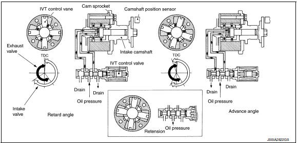
This engine is equipped with an intake valve timing controller (integral with cam sprocket) which continuously adjusts the phase of intake valve according to driving conditions, improves both low/mid range engine torque and high-speed range engine output, and brings about low emission and low fuel consumption.
The intake valve timing control system continuously controls cam phases in constant intake valve operating angle conditions and adjusts an operating oil pressure to the intake valve timing controller via the control solenoid valve.
ECM receives crankshaft position signal, camshaft position signal, engine speed signal, engine oil temperature signal, and engine coolant temperature signal. And the ECM outputs ON/OFF pulse duty signals to the intake valve timing control solenoid valve depending on driving status.
Intake Valve Timing Controller Operation List
| Intake valve timing solenoid valve condition | Intake valve timing controller operation |
| Engine OFF | When starting the engine, the controller vane and sprocket are fixed in full retard position by the reaction force of return spring, improving the starting performance of the engine. |
| Active (Advance angle) | When the energization rate to the control solenoid valve is
increased, the oil pressure from the oil
pump is conveyed to the advance angle chamber of the controller. And
retard angle chamber oil is
drained. Accordingly, the controller vane rotates rightward and the
phase of camshaft becomes advance
angle.
This condition brings about the greater overlap with the exhaust valve, enabling the exhaust gas cleaning by the internal EGR effect and the fuel consumption improvement by the reduction in pumping loss. |
| Neutral (Maintained) | When it is the target valve timing, the energization rate to the control solenoid valve is adjusted to the intermediate state. The solenoid valve is positioned at the neutral position and the oil path is interrupted to maintain the cam shaft phase. |
| Return (Retard angle) | When the energization rate to the control solenoid valve is
decreased, the oil pressure from the oil
pump is conveyed to the retard chamber of the controller. And advanced
angle chamger oil is
drained.
Accordingly, the controller vane rotates leftward and the phase of camshaft becomes retard angle. |
INTAKE VALVE TIMING CONTROL FEEDBACK CONTROL
Cam Position Detection
The camshaft position sensor mounted at the rear of the cylinder head detects a cam position, by using the groove on the plate located at the rear of the intake camshaft.
Feedback Control
The camshaft position sensor feeds back an actual cam position signal to ECM. Based on the signal, ECM controls the intake valve timing control solenoid valve to satisfy the optimum target valve opening/closing timing according to a driving condition.
 Electric ignition system
ELECTRIC IGNITION SYSTEM : System Description
SYSTEM DIAGRAM
*1: CVT models
*2: M/T models
Input/output signal chart
Sensor
Input Signal to ECM
ECM function
Actuator
...
 Exhaust valve timing control
EXHAUST VALVE TIMING CONTROL : System
Description
SYSTEM DIAGRAM
INPUT/OUTPUT SIGNAL CHART
Sensor
Input signal to ECM
ECM function
Actuator
Crankshaft position sensor ...
Other materials:
Compressor
Exploded view
With air conditioning
Compressor
Front
Without air conditioning
A/c idler pulley
A/c idler pulley bracket
Compressor
Compressor : removal and installation
REMOVAL
Discharge the refrigerant. Refer to ha-23, "recycle refrigerant".
Remove the fr ...
Basic inspection
DIAGNOSIS AND REPAIR WORKFLOW
Work Flow
DETAILED FLOW
1.LISTEN TO CUSTOMER COMPLAINT
Listen to customer complaint. Get detailed information about the conditions
and environment when the symptom
occurs.
>> GO TO 2.
2.VERIFY THE SYMPTOM WITH OPERATIONAL CHECK
Verify the symptom with ...
Checking engine coolant level
Check the coolant level in the reservoir when
the engine is cold. If the coolant level is below
the MIN level B , add coolant to the MAX level
A . If the reservoir is empty, check the coolant
level in the radiator when the engine is cold. If
there is insufficient coolant in the radiator, fi ...
