Nissan Sentra Service Manual: Electric ignition system
ELECTRIC IGNITION SYSTEM : System Description
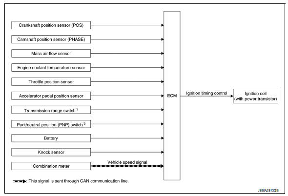
SYSTEM DIAGRAM
*1: CVT models
*2: M/T models
Input/output signal chart
| Sensor | Input Signal to ECM | ECM function | Actuator | |
| Crankshaft position sensor (POS) |
|
Ignition timing control | Ignition coil (with power transistor) | |
| Camshaft position sensor (PHASE) | ||||
| Mass air flow sensor | Amount of intake air | |||
| Engine coolant temperature sensor | Engine coolant temperature | |||
| Throttle position sensor | Throttle position | |||
| Accelerator pedal position sensor | Accelerator pedal position | |||
| Transmission range switch*1 | Gear position | |||
| Park/neutral position (PNP) switch*2 | ||||
| Battery | Battery voltage*3 | |||
| Knock sensor | Engine knocking condition | |||
| Combination meter | CAN communication | Vehicle speed signal | ||
*1: CVT models
*2: M/T models
*3: ECM determines the start signal status by the signals of engine speed and battery voltage.
SYSTEM DESCRIPTION
Firing order: 1 - 3 - 4 - 2
The ignition timing is controlled by the ECM to maintain the best air-fuel ratio for every running condition of the engine. The ignition timing data is stored in the ECM.
The ECM receives information such as the injection pulse width and camshaft position sensor (PHASE) signal.
Computing this information, ignition signals are transmitted to the power transistor.
During the following conditions, the ignition timing is revised by the ECM according to the other data stored in the ECM.
- At starting
- During warm-up
- At idle
- At low battery voltage
- During acceleration
The knock sensor retard system is designed only for emergencies. The basic ignition timing is programmed within the anti-knocking zone, if recommended fuel is used under dry conditions. The retard system does not operate under normal driving conditions. If engine knocking occurs, the knock sensor monitors the condition.
The signal is transmitted to the ECM. The ECM retards the ignition timing to eliminate the knocking condition.
 Multiport fuel injection system
MULTIPORT FUEL INJECTION SYSTEM : System
Description
SYSTEM DIAGRAM
*1: ECM determines the start signal status by the signals of engine speed and
battery voltage.
*2: M/T models
*3: CVT mod ...
 Intake valve timing control
INTAKE VALVE TIMING CONTROL : System Description
SYSTEM DIAGRAM
INPUT/OUTPUT SIGNAL CHART
Sensor
Input signal to ECM
ECM function
Actuator
Crankshaft position sensor (P ...
Other materials:
Headlamp
Aiming adjustment
Preparation before adjusting
Before performing aiming adjustment, check the following:
Ensure all tires are inflated to correct pressure.
Place vehicle and screen on level surface.
Ensure there is no load in vehicle other than the driver (or equivalent
weight placed in ...
Door switch
Component Function Check
1.Check function
Select DOOR LOCK of BCM using CONSULT
Select door sw-dr, door sw-as in data monitor mode
Check that the function operates normally according to the following
conditions.
Is the inspection result normal?
YES >> Door switch is OK.
NO ...
Basic inspection
Diagnosis and repair workflow
Work flow
OVERALL SEQUENCE
DETAILED FLOW
1.INTERVIEW FOR MALFUNCTION
Find out what the customer's concerns are.
>> GO TO 2.
2.SYMPTOM CHECK
Verify the symptom from the customer's information.
>> GO TO 3.
3.BASIC INSPECTION
Check the operat ...
