Nissan Sentra Service Manual: Steering wheel
Inspection
CONDITION OF INSTALLATION
-
Check installation condition of power steering gear assembly, front suspension, front drive shaft and steering column.
-
Check if movement exists when steering wheel is moved up and down, to the left and right and to the axial direction.
Steering wheel axial end play : Refer to ST-18, "Steering Wheel".
-
Verify that the power steering gear nuts are tightened to specification. Refer to ST-10, "Exploded View".
STEERING WHEEL PLAY
-
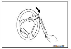
Turn tires straight ahead, start engine, then turn steering wheel to the left and right lightly. Measure steering wheel movement on the outer circumference of the steering wheel when it is turned to the point where tires start moving.
Steering wheel play : Refer to ST-18, "Steering Wheel".
NEUTRAL POSITION ON STEERING WHEEL
-
Check neutral position on steering wheel after confirming that front wheel alignment is correct. Refer to FSU- 23, "Wheel Alignment (Unladen*1)".
-
Turn tires straight ahead, check if steering wheel is in the neutral position.
-
If it is not in the neutral position, remove steering wheel and reinstall it correctly
-
If the neutral position cannot be attained by repositioning the steering wheel two teeth or less on steering stem, loosen outer socket lock nuts of power steering gear outer sockets, then adjust outer sockets by the same amount in the opposite direction.
STEERING WHEEL TURNING FORCE
-
Park vehicle on a level and dry surface, set parking brake.
-
Tires need to be inflated to normal pressure. Refer to WT-54, "Tire Air Pressure".
-
Start engine.
-
Check steering wheel turning force using Tool when steering wheel has been turned 360В° from the neutral position.
Tool number : — (J-44372)
Steering wheel turning force : Refer to ST-18, "Steering Wheel".
FRONT WHEEL TURNING ANGLE
-
P
erform toe-in inspection. Refer to FSU-6, "Inspection".
CAUTION:
Perform front wheel turning angle inspection, after toe-in inspection.
-
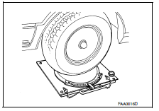
Place front wheels on turning radius gauges and rear wheels on stands, so that vehicle can be level.
-
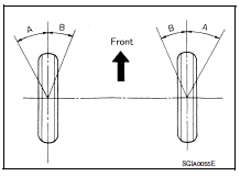
Check the maximum inner and outer wheel turning angles for (RH/LH) road wheels.
-
With the engine at idle, turn steering wheel from full left stop to full right stop and measure the turning angles.
Inner wheel (Angle: A) : Refer to ST-18, "Steering Angle".
Outer wheel (Angle: B) : Refer to ST-18, "Steering Angle".
-
Check the following items when turning angle is out of the standard.
-
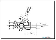
Check rack stroke (L).
(L) : Refer to ST-19, "Power Steering Gear".
-
If rack stroke is out of specification, replace steering gear assembly.
-
Steering angles are not adjustable. Check steering gear assembly, steering column assembly, and front suspension components for wear or damage if any of the turning angles are different from the specified value. Replace any of them, if any non-standard condition exists.
 Basic inspection
...
 Steering column
Inspection
STEERING COLUMN ASSEMBLY
Check each part of steering column assembly for damage or
other malfunctions. Replace entire steering column
assembly if any parts are damaged.
Me ...
Other materials:
P2004 Intake manifold runner control valve
DTC Logic
DTC DETECTION LOGIC
DTC No.
CONSULT screen terms
(Trouble diagnosis content)
DTC detecting condition
Possible cause
P2004
TUMBLE CONT/V
(Intake manifold runner control
stuck open bank 1)
The target angle of intake manifold runner
control valve c ...
Basic inspection
DIAGNOSIS AND REPAIR WORK FLOW
Work Flow
NOTE:
“DTC” includes DTC at the 1st trip.
1.OBTAIN INFORMATION ABOUT SYMPTOM
Refer to TM-140, "Diagnostic Work Sheet" and interview the customer to obtain
the malfunction information
(conditions and environment when the malfunctio ...
Seat belt warning system
Seat Belt Warning System Does Not Function
1.SEAT BELT WARNING LIGHT
Turn ignition switch ON.
Does the seat belt warning lamp come ON?
YES >> GO TO 2.
NO >> • Check 10A fuse [No. 8, located in the fuse block (J/B)].
Check seat belt buckle switch (driver seat)
Check ha ...
