Nissan Sentra B18 (2020-2025) Service Manual: Heated Seat System
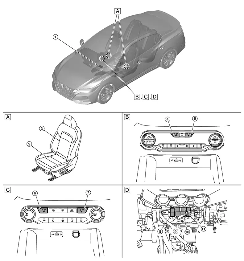
Component Parts Location
|
A. |
Front seat LH (front power seat LH shown, front manual seat RH similar) |
B. |
A/C switch assembly (with auto A/C) |
C. |
A/C switch assembly (with manual A/C) |
|
D. |
Center of instrument panel (view with instrument panel finisher removed) |
||||
|
No. |
Component |
Function |
|---|---|---|
|
1. |
A/C auto amp. (with auto A/C) |
Controls the heated seat high and low relays. Refer to A/C auto amp. (with auto A/C) or A/C amp. (with manual A/C) for detailed component location. |
|
A/C amp. (with manual A/C) |
||
|
2. |
Cushion heater LH (RH similar) |
Refer to Front Seat Heaters. |
|
3. |
Seat heater LH (back) (RH similar) |
|
|
4. |
Heated seat switch LH (with auto A/C) |
Refer to A/C Switch Assembly for detailed component location. |
|
5. |
Heated seat switch RH (with auto A/C) |
|
|
6. |
Heated seat switch LH (with manual A/C) |
Refer to A/C Switch Assembly for detailed component location. |
|
7. |
Heated seat switch RH (with manual A/C) |
|
|
8. |
Heated seat LH low relay |
Activates heated seat LH (LOW) with relay activation signal from the A/C auto amp. (with auto A/C) or A/C amp. (with manual A/C). |
|
9. |
Heated seat LH high relay |
Activates heated seat LH (HIGH) with relay activation signal from the A/C auto amp. (with auto A/C) or A/C amp. (with manual A/C). |
|
10. |
Heated seat RH low relay |
Activates heated seat RH (LOW) with relay activation signal from the A/C auto amp. (with auto A/C) or A/C amp. (with manual A/C). |
|
11. |
Heated seat RH high relay |
Activates heated seat RH (HIGH) with relay activation signal from the A/C auto amp. (with auto A/C) or A/C amp. (with manual A/C). |
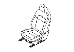
Front Seat Heater
-
Front seat heaters are installed inside the front seat cushion and seat back.
(Front power seat LH shown, front manual seat RH similar)
-
The front seat heaters operate with power source provided via the heated seat high and low relays.
 Power Seat System
Component Parts Location
Component Parts
Location
No.
Component
Funct ...
 System
...
Other materials:
Adas Control Unit 2
List of Ecu Reference
List of ECU Reference
ECU
Reference
ADAS control unit 2
Values On The Diagnosis Tool
...
Dtc Diagnosis Procedure
DTC Diagnosis
Procedure
Note:
The Signal Tech II Tool [– (NI-50190)] can be used
to perform the following functions: Refer to the Signal Tech II User
Guide for additional information.
Activate and display TPMS sensor IDs
Display tire pressure reported ...
Preparation
Special Service Tool
The actual shape of the tools may differ from those illustrated here.
Commercial Service Tools
Clip list
Descriptions for Clips
Replace any clips which are damaged during removal or installation.
...
