Nissan Sentra B18 (2020-2025) Service Manual: Seat :: System Description
Component Parts. Power Seat System
Component Parts Location
Component Parts Location
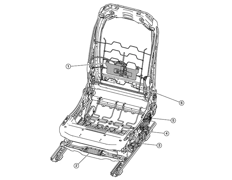
|
No. |
Component |
Function |
|---|---|---|
|
1. |
Lumbar support motor |
Refer to Lumbar Support Motor. |
|
2. |
Sliding motor LH |
Refer to Sliding Motor LH. |
|
3. |
Power seat switch LH |
Refer to Power Seat Switch LH. |
|
4. |
Lumbar support switch |
Refer to Lumbar Support Switch. |
|
5. |
Lifting motor LH |
Refer to Lifting Motor LH. |
|
6. |
Reclining motor LH |
Refer to Reclining Motor LH. |
Sliding Motor Lh
Sliding Motor LH
-
The sliding motor LH is installed to the seat frame assembly LH.
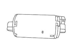
-
The seat is moved forward/backward by changing the rotation direction of the sliding motor LH.
Reclining Motor Lh
Reclining Motor LH
-
The reclining motor LH is installed to the seat back assembly LH.
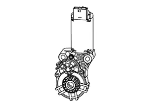
-
The seatback is reclined forward/backward by changing the rotation direction of reclining motor LH.
Lifting Motor Lh
Lifting Motor LH
-
The lifting motor LH is installed to seat frame assembly LH.
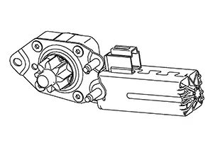
-
The seat is moved upward/downward by changing the rotation direction of lifting motor LH.
Lumbar Support Motor
Lumbar Support Motor
-
The lumbar support motor is installed on the seat back assembly LH.
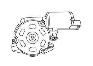
-
With power supplied to the lumbar support switch, the lumbar support motor operates and makes forward and backward position adjustment of the seat back support possible.
Power Seat Switch Lh
Power Seat Switch LH
-
The power seat switch LH is installed on seat cushion outer finisher LH.
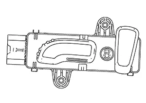
-
Built-in reclining switch, sliding switch and lifting switch, controls the power supplied to each power seat motor.
Lumbar Support Switch
Lumbar Support Switch
-
The lumbar support switch is installed on seat cushion outer finisher LH.
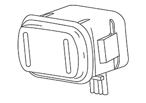
-
The lumbar support switch controls the power supplied to the lumbar support motor.
Heated Seat System
Component Parts Location
Component Parts Location
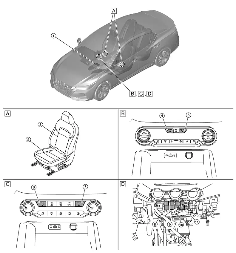
|
A. |
Front seat LH (front power seat LH shown, front manual seat RH similar) |
B. |
A/C switch assembly (with auto A/C) |
C. |
A/C switch assembly (with manual A/C) |
|
D. |
Center of instrument panel (view with instrument panel finisher removed) |
||||
|
No. |
Component |
Function |
|---|---|---|
|
1. |
A/C auto amp. (with auto A/C) |
Controls the heated seat high and low relays. Refer to A/C auto amp. (with auto A/C) or A/C amp. (with manual A/C) for detailed component location. |
|
A/C amp. (with manual A/C) |
||
|
2. |
Cushion heater LH (RH similar) |
Refer to Front Seat Heaters. |
|
3. |
Seat heater LH (back) (RH similar) |
|
|
4. |
Heated seat switch LH (with auto A/C) |
Refer to A/C Switch Assembly for detailed component location. |
|
5. |
Heated seat switch RH (with auto A/C) |
|
|
6. |
Heated seat switch LH (with manual A/C) |
Refer to A/C Switch Assembly for detailed component location. |
|
7. |
Heated seat switch RH (with manual A/C) |
|
|
8. |
Heated seat LH low relay |
Activates heated seat LH (LOW) with relay activation signal from the A/C auto amp. (with auto A/C) or A/C amp. (with manual A/C). |
|
9. |
Heated seat LH high relay |
Activates heated seat LH (HIGH) with relay activation signal from the A/C auto amp. (with auto A/C) or A/C amp. (with manual A/C). |
|
10. |
Heated seat RH low relay |
Activates heated seat RH (LOW) with relay activation signal from the A/C auto amp. (with auto A/C) or A/C amp. (with manual A/C). |
|
11. |
Heated seat RH high relay |
Activates heated seat RH (HIGH) with relay activation signal from the A/C auto amp. (with auto A/C) or A/C amp. (with manual A/C). |
Front Seat Heater
Front Seat Heater
-
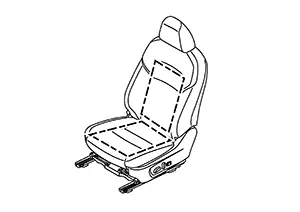
Front seat heaters are installed inside the front seat cushion and seat back.
(Front power seat LH shown, front manual seat RH similar)
-
The front seat heaters operate with power source provided via the heated seat high and low relays.
System. Power Seat System
System Description
System Description
DESCRIPTION
Power seat can be operated regardless of the ignition switch status, because power supply is always supplied to power seat switch.
Sliding Operation
While operating the sliding switch located in the power seat switch, the sliding motor operates and makes seat forward and backward position adjustment possible.
Reclining Operation
While operating the reclining switch located in the power seat switch, the reclining motor operates and makes seat back forward and backward position adjustment possible.
Lifting Operation
While operating the lifting switch located in the power seat switch, the lifting motor operates and makes seat up and down position adjustment possible.
Lumbar Support System
System Description
System Description
DESCRIPTION
-
Lumbar support can operate regardless of the ignition switch status, because power supply is always supplied to the lumber support switch.
-
While operating the lumbar support switch, the lumbar support motor operates which makes forward and backward position adjustment of the seat back support possible.
Heated Seat System
System Description (with Auto A/c)
System Description (With Auto A/C)
SYSTEM DIAGRAM
OUTLINE
-
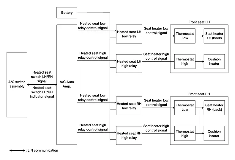
The heated seat system (LH and RH) consists of the heated seat high relays, heated seat low relays, heated seat switch, the A/C switch assembly, the A/C auto amp. and the front seat heaters.
-
The heated seat switch changes ON/OFF operation and HIGH/LOW mode of heated seat system.
-
The heated seat switch has HIGH/LOW indicators which indicate system operation condition.
Signal transmission function list
|
Signal name |
Input |
Output |
Description |
|---|---|---|---|
|
Heated seat switch LH/RH signal |
A/C switch assembly |
A/C auto amp. (LIN) |
Transmits the heated seat switch LH/RH signal via LIN communication. |
|
Heated seat switch LH/RH indicator signal |
A/C auto amp. |
A/C switch assembly (LIN) |
Transmits the heated seat switch LH/RH indicator signal via LIN communication. |
DESCRIPTION
-
The heated seat system is activated by the A/C switch assembly (heated seat switch) when the ignition switch is ON, and has the function to warm the seat cushion and seat back.
-
The heated seat system operates with the heated seat switch integrated with the A/C switch assembly.
-
The heated seat system operates the front seat LH and front seat RH independently.
-
The temperature of the heated seat system can be set in two levels: HIGH and LOW.
-
The operation status of the heated seat system can be checked by checking the indicators of the heated seat switches integrated with the A/C switch assembly.
OPERATION DESCRIPTION
-
When the heated seat switch is operated, the A/C auto amp. receives a switch operation signal from heated seat switch.
-
The A/C switch assembly transmits a heated seat switch operation signal to the A/C auto amp. via LIN communication.
-
When the A/C auto amp. receives a heated seat switch operation signal, it operates the heated seat high/low relays and the heated seat system.
-
When the A/C switch assembly receives a heated seat switch indicator signal, it illuminates the indicator lamp on the heated seat switch.
System Description (with Manual A/c)
System Description (With Manual A/C)
SYSTEM DIAGRAM
OUTLINE
-
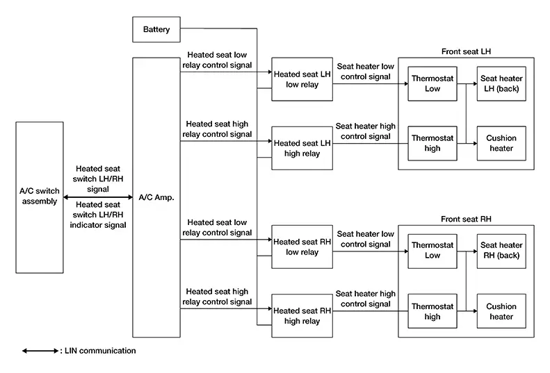
The heated seat system (LH and RH) consists of the heated seat high relays, heated seat low relays, heated seat switch, the A/C switch assembly, the A/C amp. and the front seat heaters.
-
The heated seat switch changes ON/OFF operation and HIGH/LOW mode of heated seat system.
-
The heated seat switch has HIGH/LOW indicators which indicate system operation condition.
Signal transmission function list
|
Signal name |
Input |
Output |
Description |
|---|---|---|---|
|
Heated seat switch LH/RH signal |
A/C switch assembly |
A/C amp. (LIN) |
Transmits the heated seat switch LH/RH signal via LIN communication |
|
Heated seat switch LH/RH indicator signal |
A/C amp. |
A/C switch assembly (LIN) |
Transmits the heated seat switch LH/RH indicator signal via CAN communication. |
DESCRIPTION
-
The heated seat system is activated by the A/C switch assembly (heated seat switch) when the ignition switch is ON, and has the function to warm the seat cushion and seat back.
-
The heated seat system operates with the heated seat switch integrated with the A/C switch assembly.
-
The heated seat system operates the front seat LH and front seat RH independently.
-
The temperature of the heated seat system can be set in two levels: HIGH and LOW.
-
The operation status of the heated seat system can be checked by checking the indicators of the heated seat switches integrated with the A/C switch assembly.
OPERATION DESCRIPTION
-
When the heated seat switch is operated, the A/C amp. receives a switch operation signal from heated seat switch.
-
The A/C switch assembly transmits a heated seat switch operation signal to the A/C amp. via LIN communication.
-
When the A/C amp. receives a heated seat switch operation signal, it operates the heated seat high/low relays and the heated seat system.
-
When the A/C switch assembly receives a heated seat switch indicator signal, it illuminates the indicator lamp on the heated seat switch.
Diagnosis System (a/c Auto Amp.) (with Auto A/c). Consult Function (hvac). Consult Function (hvac)
CONSULT Function (HVAC)
|
A/C auto amp. |
Refer to CONSULT Function (HVAC). |
Diagnosis System (a/c Amp.) (with Manual A/c). Consult Function (hvac). Consult Function (hvac)
CONSULT Function (HVAC)
|
A/C amp. |
Refer to CONSULT Function (HVAC). |
Other materials:
Rear window and outside mirror defroster switch
To defrost the rear window glass and the outside mirrors (if so equipped), start
the engine and press the rear window defroster switch. The indicator light on the
switch will illuminate while the system is active. Press the switch again to turn
the defroster off.
The rear window defroster ...
Selector Lever Knob
Selector Lever Knob: Removal & Installation
SELECTOR LEVER
KNOB: Removal & Installation
REMOVAL
Slide the shift selector finisher
boot (3) down.
Using a suitable tool, remove the
lock pin (2) by pulling it toward the front of Nissan Sentra vehicle.
Note:
...
Rear Axle. Service Data and Specifications (sds). Service Data and Specifications (sds). Wheel Bearing
Service Data and Specifications (sds). Wheel Bearing
Wheel Bearing
Wheel Bearing
Item
Standard
Axial end play
0.05 mm (0.002 in) or
...