Nissan Sentra B18 (2020-2025) Service Manual: Fuel Injector
Component Function Check
Component Function Check
-
INSPECTION START
Turn ignition switch to START.
Are any cylinders ignited?
YES >>GO TO 2.
NO >>Refer to Diagnosis Procedure.
-
CHECK FUEL INJECTOR FUNCTION
 With CONSULT
-
Start engine.
-
Perform ŌĆ£POWER BALANCEŌĆØ in ŌĆ£ACTIVE TESTŌĆØ mode of ŌĆ£ENGINEŌĆØ with CONSULT.
-
Check that each circuit produces a momentary engine speed drop.
 Without CONSULT
-
Start engine and let it idle.
-
Listen to each fuel injector operating sound.
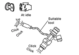
Clicking sound should be heard.
Is the inspection result normal?
YES >>INSPECTION END
NO >>Refer to Diagnosis Procedure.
-
Diagnosis Procedure
Diagnosis Procedure
-
CHECK FUSE
-
Turn ignition switch OFF.
-
Check that the following fuse is not blowing.
Fuse No.
Capacity
#60
10A
#64
15 A
Is the fuse blown (open)?
YES >>Replace the fuse after repairing the applicable circuit.
NO >>GO TO 2.
-
-
CHECK FUEL INJECTOR DRIVER POWER SUPPLY
-
Disconnect ECM harness connector.
-
Turn ignition switch ON.
-
Check the voltage between ECM harness connector and ground.
+
ŌłÆ
Voltage
ECM
Connector
Terminal
F24
3
Ground
Battery voltage
4
Is the inspection result normal?
YES >>GO TO 9.
NO >>GO TO 3.
-
-
CHECK FUEL INJECTOR DRIVER POWER SUPPLY CIRCUIT
-
Turn ignition switch OFF.
-
Disconnect ECM harness connector.
-
Disconnect direct fuel injector relay 1 and 2 harness connector.
-
Check the continuity between ECM harness connector and direct fuel injector relay 1 and 2 harness connector.
ECM
Direct fuel injector relay 1 and 2
Continuity
Connector
Terminal
Connector
Terminal
F24
3
F60
2
Existed
4
7
-
Also check harness for short to ground and short to power.
Is the inspection result normal?
YES >>GO TO 4.
NO >>Repair or replace malfunctioning part.
-
-
CHECK DIRECT FUEL INJECTOR RELAY 1 AND 2 POWER SUPPLY (CONTACT SIDE)
Check the voltage between fuel injector relay harness connector and ground.
+
ŌłÆ
Voltage
Direct fuel injector relay 1 and 2
Connector
Terminal
F60
1
Ground
Battery voltage
6
Is the inspection result normal?
YES >>GO TO 5.
NO >>Perform trouble diagnosis for power supply circuit.
-
CHECK DIRECT FUEL INJECTOR RELAY 1 AND 2 POWER SUPPLY (EXCITATION COIL SIDE)
-
Install all removed parts.
-
Turn ignition switch ON.
-
Check the voltage between direct fuel injector relay 1 and 2 harness connector and ground.
+
ŌłÆ
Voltage
Direct fuel injector relay 1 and 2
Connector
Terminal
F60
3
Ground
Battery voltage
8
Is the inspection result normal?
YES >>GO TO 7.
NO >>GO TO 6.
-
-
CHECK DIRECT FUEL INJECTOR RELAY 1 AND 2 POWER SUPPLY CIRCUIT (EXCITATION COIL SIDE)
-
Turn ignition switch OFF.
-
Disconnect direct fuel injector relay 1 and 2 harness connector.
-
Disconnect IPDM E/R harness connector.
-
Check the continuity between IPDM E/R harness connector and fuel injector relay harness connector.
IPDM E/R
Direct fuel injector relay 1 and 2
Continuity
Connector
Terminal
Connector
Terminal
F96
73
F60
3
Existed
8
-
Also check harness for short to ground and short to power.
Is the inspection result normal?
YES >>Perform trouble diagnosis for power supply circuit.
NO >>Repair or replace malfunctioning part.
-
-
CHECK FUEL INJECTOR RELAY GROUND CIRCUIT
-
Turn ignition switch OFF.
-
Disconnect fuel injector relay harness connector.
-
Check the continuity between direct fuel injector relay 1 and 2 harness connector and ground.
Direct fuel injector relay 1 and 2
ŌĆö
Continuity
Connector
Terminal
F60
4
Ground
Existed
9
-
Also check harness for short to power.
Is the inspection result normal?
YES >>GO TO 8.
NO >>Repair or replace malfunctioning part.
-
-
CHECK DIRECT FUEL INJECTOR RELAY 1 AND 2
Refer to Component Inspection.
Is the inspection result normal?
YES >>Check intermittent incident. Refer to Intermittent Incident.
NO >>Replace direct fuel injector relay 1 and 2.
-
CHECK ECM GROUND CIRCUIT
-
Turn ignition switch OFF.
-
Check the continuity between ECM harness connector and ground.
ECM
ŌĆö
Continuity
Connector
Terminal
F24
5
Ground
Existed
65
F25
69
E16
157
159
162
-
Also check harness for short to power.
Is the inspection result normal?
YES >>GO TO 10.
NO >>Repair or replace malfunctioning part.
-
-
CHECK FUEL INJECTOR GROUND CIRCUIT
-
Turn ignition switch OFF.
-
Disconnect ECM harness connector.
-
Check the continuity between fuel injector harness connector and ECM harness connector.
Fuel injector
ECM
Continuity
Cylinder
Connector
Terminal
Connector
Terminal
1
F18
2
F24
8
Existed
2
F19
2
7
3
F20
2
9
4
F21
2
6
-
Also check harness for short to ground.
Is the inspection result normal?
YES >>GO TO 11.
NO >>Repair or replace malfunctioning part.
-
-
CHECK FUEL INJECTOR
Refer to Component Inspection.
Is the inspection result normal?
YES >>Check intermittent incident. Refer to Intermittent Incident.
NO >>Replace malfunctioning fuel injector. Refer to Removal and Installation.
Component Inspection
Component Inspection
-
CHECK FUEL INJECTOR
-
Turn ignition switch OFF.
-
Disconnect fuel injector harness connector.
-
Check the resistance between fuel injector terminals.
Fuel injector
Condition
Resistance
Terminal
1
2
Temperature
20┬░C (68┬░F)
1.34 ŌĆō 1.64 Ōä”
Is the inspection result normal?
YES >>INSPECTION END
NO >>Replace fuel injector. Refer to Component Parts Location.
-
Other materials:
Security systems
Your Nissan Sentra may be equipped with two different types of security systems
designed to enhance vehicle protection and theft deterrence:
Vehicle security system (if so equipped)
NISSAN Vehicle Immobilizer System
Vehicle security system
The vehicle security system on the Nissan Se ...
Side Radar Right (side Radar Rh)
C1e80-44 Control Unit
Dtc Description
DTC Description
DTC DETECTION LOGIC
DTC No.
CONSULT screen terms
(Trouble diagnosis
content)
DTC detecti ...
Component Parts
Display Audio Without Bose with 8" Color Display
Component Parts Location
Component Parts Location
No.
Component
Function
...