Nissan Sentra B18 (2020-2025) Service Manual: Front Wheel Hub
Exploded View
Exploded View
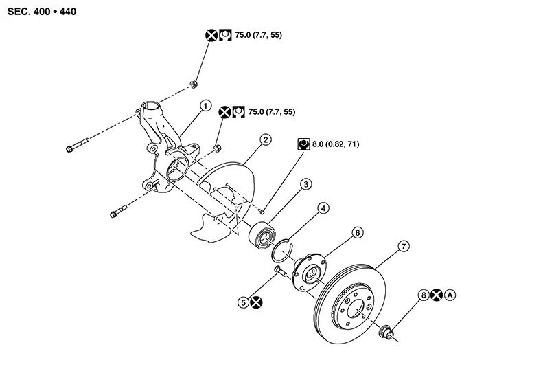
|
1. |
Steering knuckle |
2. |
Splash guard |
3. |
Wheel bearing |
|
4. |
Snap ring |
5. |
Wheel stud |
6. |
Wheel hub |
|
7. |
Disc brake rotor |
8. |
Wheel hub lock nut |
A. |
Refer to Removal and Installation. |
Removal and Installation
Removal and Installation
REMOVAL
Remove steering knuckle. Refer to Removal and Installation.
Remove
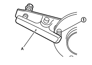
wheel studs (1) from wheel hub, using suitable tool [A (if
necessary)].
CAUTION:
-
Remove wheel studs only when necessary.
-
Do not reuse wheel studs.
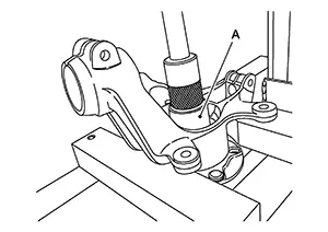
Remove
wheel hub using Tool (A).
|
Tool number |
: ST33710000 ( — ) |
Remove splash guard from steering knuckle.
CAUTION:
Do not reuse splash guard.
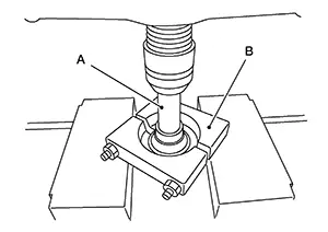
Remove
wheel bearing inner race (outer side) from wheel hub, using Tools
(A) and (B).
|
Tool number (A) |
: ST33710000 ( — ) |
|
Tool number (B) |
: ST30031000 ( — ) |
Remove snap ring from steering knuckle using suitable tool.
CAUTION:
Do not damage steering knuckle.
Remove
wheel bearing from steering knuckle using Tool (A).
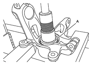
|
Tool number |
: ST35321000 ( — ) |
If
necessary, remove the wheel studs (1) from the wheel hub and
bearing using a suitable tool (A).
CAUTION:
-
Remove the wheel studs only when necessary.
-
Do not hammer the wheel studs or damage to the wheel hub and bearing may occur.
-
Pull out the wheel stud in a direction perpendicular to the wheel hub and bearing.
-
Do not reuse wheel stud.
Inspect the components. Refer to Inspection.
INSPECTION AFTER REMOVAL
Wheel Hub
-
Check wheel hub for wear, cracks or deformation. Replace wheel hub if damaged.
Steering Knuckle
-
Check steering knuckle for deformation, cracks, and other damage. Replace steering knuckle if damaged.
Snap Rings
-
Check snap ring for wear or cracks. Replace if damage is detected.
INSTALLATION
Install wheel bearing into
steering knuckle using Tool (A) and suitable tool (B).
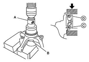
|
Tool number |
: ST35271000 ( — ) |
CAUTION:
-
Do not reuse wheel bearing.
-
Install wheel bearing with wheel speed sensor encoder [(rubber part) (C)] facing inner side of steering knuckle.
|
(D) |
:Bearing outer seal |
Apply press-fit load to wheel bearing outer race and steering knuckle.
|
Press fit load |
: Refer to Wheel Bearing. |
CAUTION:
Press-fit load must be applied only to wheel bearing outer race and steering knuckle to prevent bearing damage.
Install snap ring into steering knuckle outer groove.
CAUTION:
-
Do not damage the wheel bearing outer seal.
-
Snap ring must be installed evenly into the groove.
If removed, install wheel studs
into wheel hub.
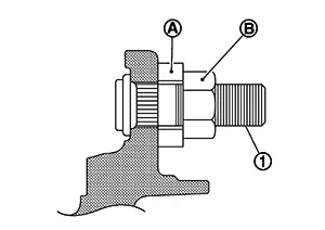
Place washer (A) as shown to install wheel studs (1) by using tightening force of nut (B).
CAUTION:
-
Do not reuse wheel studs.
-
Check that there is no clearance between wheel stud and wheel hub and bearing.
Install wheel hub, using Tools
(A) and (B).
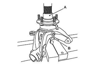
|
Tool number (A) |
: ST33061000 ( — ) |
|
Tool number (B) |
: ST35321000 ( — ) |
CAUTION:
-
Do not apply lubricating oil to press-fit surfaces of wheel hub and bearing.
-
Set steering knuckle and wheel bearing horizontally and insert them vertically.
-
Press-fit load must be applied to wheel bearing inner race and wheel hub.
-
Do not apply press-fit load to steering knuckle and wheel bearing seal. If a press-fit load is applied, wheel bearing must be replaced with a new one.
-
If inserted wheel hub is removed again, wheel bearing must be replaced with a new one.
Press wheel
hub (1) into wheel bearing (2) until surface (A) contacts surface
(B).
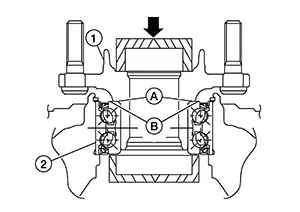
CAUTION:
Apply a press-fit load only to wheel bearing inner race and wheel hub to prevent bearing damage.
|
Press fit load |
: Refer to Wheel bearing. |
INSPECTION AFTER INSTALLATION
Check wheel bearing rotating torque as per the following instructions.
Note:
The adequacy of turning torque can be judged from a measurement value by a suitable tool.
For a proper fit of bearing, rotate wheel hub both clockwise and counterclockwise, respectively, 10 times or more with press-fit load applied.
|
Press fit load |
: Refer to Wheel bearing. |
Set
suitable tool on strut mounting hole (upper). Measure rotating
torque at a speed of 8 - 12 rpm.
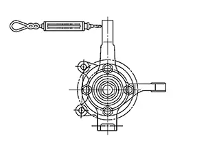
|
Rotating torque |
: Refer to Wheel bearing. |
|
Spring balance measurement |
: Refer to Wheel bearing. |
-
If the turning torque cannot be obtained by the above method, measure the torque according to the instructions below.
-
Install drive shaft and tighten the hub lock nut to the specified torque. Rotate the wheel hub to fit properly.
-
Set a suitable tool on a wheel nut and measure turning torque at turning speeds of 8 to 12 rpm.
Rotating torque
: Refer to Wheel bearing.
-
Installation of the remaining components is in the reverse order of removal.
Inspection
Inspection
INSPECTION AFTER REMOVAL
Check the following items, and replace the part if necessary.
-
Check components for deformation, cracks, and other damage.
-
Check boots of transverse link and steering outer socket ball joint for breakage, axial end play, and swing torque.
-
Transverse link: Refer to Inspection.
-
Steering outer socket: Refer to Inspection.
-
INSPECTION AFTER INSTALLATION
Check the wheel sensor harness to be sure the connectors are fully seated.
Check the wheel alignment. Refer to Inspection.
Other materials:
Decel G Sensor Calibration
Description
Description
TCM stores calibration data (inherent characteristic value) of
decel G sensor to provide accurate control.
Therefore, it is required to perform calibration of decel G sensor
after the following work is performed.
Removing/ installing ABS actuator ...
B2033-4a Dongle Ng
Dtc Description
DTC Description
DTC DETECTION LOGIC
DTC No.
CONSULT screen items
(Trouble diagnosis
content)
DTC detection condition
...
B20ce-15 Hl (hi) Lh Pwr Sply Circ
Dtc Description
DTC Description
DTC DETECTION LOGIC
DTC No.
CONSULT screen items
(Trouble diagnosis content)
DTC detection condition
...