Nissan Sentra Service Manual: Front disc brake
BRAKE PAD
BRAKE PAD : Inspection
PAD WEAR
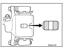
Check brake pad thickness from an inspection hole on caliper body.
Check using a scale if necessary
Wear limit thickness : Refer to BR-55, "Front Disc Brake".

DISC ROTOR
DISC ROTOR : Inspection
APPEARANCE
Check surface of disc rotor for uneven wear, cracks or damage. Replace if any abnormal conditions exist.
RUNOUT
- Check the wheel bearing axial end play before the inspection. Refer to FAX-6, "Inspection".
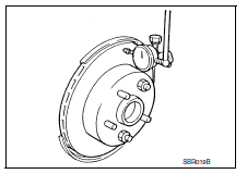
- Secure the disc rotor to the wheel hub and bearing assembly with wheel nuts at two wheel nut locations.
- Inspect the runout with a dial gauge, measured at 10 mm (0.39 in) inside the disc edge.
Runout : Refer to BR-55, "Front Disc Brake".
- Find the installation position with a minimum runout by shifting the disc rotor-to-wheel hub and bearing assembly installation position by one hole at a time if the runout exceeds the limit value.
- Refinish the disc rotor if the runout is outside the limit even after performing the above operation. When refinishing, use Tool.

Tool number : 38-PFM92 ( — )
THICKNESS
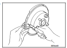
Check the thickness of the disc rotor using a micrometer. Replace the disc rotor if the thickness is below the wear limit.
Wear thickness : Refer to BR-55, "Front Disc Brake".
Thickness variation : Refer to BR-55, "Front Disc Brake".

 Brake booster
Inspection
Operation
Depress the brake pedal several times at five second intervals with
the engine stopped. Start the engine with the brake pedal fully
depressed. Check that the clearance between ...
 Rear drum brake
BRAKE LINING
BRAKE LINING : Inspection
INSPECTION
Brake Lining
Check brake lining wear thickness (A). Check using a scale if
necessary.
Lining wear thickness (A) : Refer to BR-55, "Re ...
Other materials:
P0181 FTT Sensor
DTC Logic
DTC DETECTION LOGIC
DTC No.
CONSULT screen terms
(Trouble diagnosis content)
DTC detecting condition
Possible cause
P0181
FTT SENSOR
(Fuel temperature sensor ″A″
circuit range/performance)
A)
Rationally incorrect voltage from the
...
Application Download
Once connected, the NissanConnect™ App will
search your phone to determine which compatible
applications are currently installed. The user
will then choose which apps they want to bring
into their vehicle from the list of apps within the
“Manage My Apps” section of the NissanConnect
™ ...
Precaution for Liquid Gasket
REMOVAL OF LIQUID GASKET
After removing nuts and bolts, separate the mating surface, using Tool
and remove old liquid gasket.
Tool number : KV10111100 (J-37228)
CAUTION:
Be careful not to damage the mating surfaces.
Tap (1) Tool to insert it, and then slide it (2) by tapping on t ...
