Nissan Sentra B18 (2020-2025) Service Manual: Front Combination Lamp
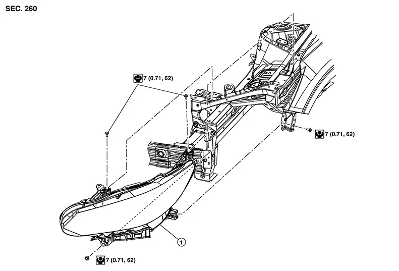
Exploded View
|
1. |
Front combination lamp |
Removal and Installation
REMOVAL
Remove front bumper fascia. Refer to Removal and Installation.
Remove front combination lamp bolts.
Pull front combination lamp forward.
Disconnect harness connectors from front combination lamp and remove.
INSTALLATION
Installation is in the reverse order of removal.
Note:
After installation, perform headlamp aiming adjustment. Refer to Aiming Adjustment.
Bulb Replacement
Warning:
Do not touch bulb with hand while it is lit or right after being turned off. Burning may result.
CAUTION:
-
Do not touch glass surface of bulb with bare hands or allow oil or grease to get on it to prevent damage to bulb.
-
Do not leave bulb out of lamp reflector for a long time because dust, moisture, smoke, etc. may affect performance of lamp. When replacing bulb, be sure to replace it with new one.
-
After installing bulb, install bulb socket securely for watertightness.
HEADLAMP (LOW BEAM) BULB
The headlamp (low beam) bulb is LED and not serviced separately. Refer to Removal and Installation.
HEADLAMP (HIGH BEAM) BULB
The headlamp (high beam) bulb is LED and not serviced separately. Refer to Removal and Installation.
SIDE MARKER LAMP BULB
The side marker lamp bulb is LED and is serviced as an assembly to the front combination lamp. Refer to Removal and Installation.
DAYTIME RUNNING LAMP BULB
The daytime running lamp bulb is LED and is serviced as an assembly to the front combination lamp. Refer to Removal and Installation.
TURN/PARKING LAMP BULB
Removal
Remove front combination lamp. Refer to Removal and Installation.
Rotate turn/parking lamp bulb socket counterclockwise and remove from front combination lamp.
Remove turn/parking lamp bulb from bulb socket.

 Front Fog Lamp
Exploded View
Exploded View
1.
Front bumper fascia
2 ...
Other materials:
Front door
Door assembly
Door assembly : removal and installation
CAUTION:
Use two people when removing or installing the front door assembly
due to its heavy weight.
When removing and installing front door assembly, support front
door using a suitable tool.
Do not use air tools or electric to ...
Power Supply and Ground Circuit
Av Control Unit
Diagnosis Procedure
Diagnosis Procedure
CHECK FUSE
Check that the following fuse is not blown:
...
Exploded View
Exploded View
1.
Steering column
2.
Lower joint
3.
Steering gear
...
