Nissan Sentra B18 (2020-2025) Service Manual: Exhaust System :: Removal and Installation. Exhaust System
Exhaust System. Exploded View
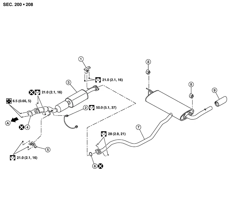
Exploded View
|
1. |
Mounting rubber |
2. |
Heated oxygen sensor 2 |
3. |
Exhaust front tube |
|
4. |
Plate gasket |
5. |
Mounting rubber |
6. |
Seal bearing |
|
7. |
Exhaust main muffler |
8. |
Mounting rubber |
9. |
Exhaust finisher (if equipped) |
|
A. |
To exhaust manifold. Refer to Exploded View. |
CAUTION:
Do not remove the heated oxygen sensor 2 from the front exhaust tube unless necessary for replacement of the heated oxygen sensor 2. If the heated oxygen sensor 2 is removed from the front exhaust tube, it must be replaced with a new one.
Note:
Heated oxygen sensor 2 replacement or removal from the front exhaust tube is not necessary when removing or repositioning the front exhaust tube. Disconnect the harness connector from the heated oxygen sensor 2 and remove or reposition the front exhaust tube and the heated oxygen sensor 2 as an assembly.
Removal and Installation
Removal and Installation
REMOVAL
Disconnect each joint and mounting rubber.
-
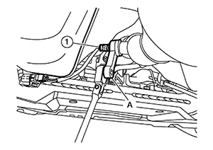
Remove heated oxygen sensor 2 (1) using Tool (A).
 :
Front
:
FrontTool number (A)
: KV10114400 (NI-38365)
CAUTION:
-
Discard any heated oxygen sensor which has been dropped from a height of more than 0.5 m (19.7 in) onto a hard surface such as a concrete floor, use a new one.
-
Before installing new heated oxygen sensor, clean exhaust system threads using oxygen sensor thread cleaner and approved anti-seize lubricant.
Oxygen sensor thread cleaner
: — (NI-43897-12)
Oxygen sensor thread cleaner
: — (NI-43897-18)
-
INSTALLATION
Installation is in the reverse order of removal.
CAUTION:
-
Do not reuse seal bearing.
-
Do not reuse plate gasket.
-
Discard any heated oxygen sensor 2 which has been dropped onto a hard surface such as a concrete floor. Use a new one.
-
Before installing a new heated oxygen sensor 2, clean exhaust system threads using the oxygen sensor thread cleaner and apply anti-seize lubricant.
-
Do not over tighten heated oxygen sensor 2. Doing so may cause damage to the heated oxygen sensor 2, resulting in the “MIL” coming on.
-
Prevent rust preventives from adhering to the sensor body.
-
If heat insulator is badly deformed, repair or replace it. If deposits such as mud pile up on the heat insulator, remove them.
-
When installing heat insulator avoid large gaps or interference between heat insulator and each exhaust pipe.
-
Remove deposits from the sealing surface of each connection. Connect them securely to avoid gas fume leaks.
-
When installing each mounting rubber, use silicon oil to avoid twisting.
-
Temporarily tighten nuts and bolts. Check each part for unusual interference and mounting rubber interference, and then tighten them to the specified torque.
-
When installing each mounting rubber, avoid twisting or unusual extension in up/down, front/rear and right/left directions.
Exhaust Manifold to Exhaust Front Tube
Securely
insert plate gasket (2) into exhaust manifold (1) in the direction
shown. 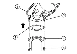
|
(3) |
: Stud bolt |
|
(4) |
: Exhaust front tube |
|
(5) |
: Nut |
CAUTION:
Do not reuse plate gasket.
Be careful not to damage plate gasket surface when installing.
Install exhaust front tube and tighten nut.
CAUTION:
-
Fasten stud bolts to the flange of exhaust manifold side to the specified torque before installing nuts.
-
Be careful that stud bolt does not interfere with hole of exhaust front tube.
After installing, check that stud bolt does not interfere with hole of exhaust front tube.
Exhaust Front Tube to Exhaust Main Muffler
Securely
insert seal bearing (3) into exhaust front tube (1) in the
direction shown. 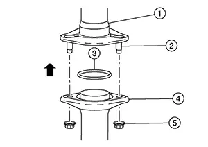
|
(2) |
: Stud bolt |
|
(4) |
: Exhaust main muffler |
|
(5) |
: Nut |
CAUTION:
Do not reuse seal bearing.
Be careful not to damage seal bearing surface when installing.
Install exhaust main muffler and tighten nut.
CAUTION:
-
Be careful that stud bolt does not interfere with hole of main muffler.
After installing, check that the stud bolt does not interfere with hole of main muffler.
Inspection
Inspection
INSPECTION AFTER INSTALLATION
Check clearance between tail tube and rear bumper is even.
With engine running, check exhaust tube joints for gas fume leaks and unusual noises.
Check to ensure that mounting brackets and mounting rubbers are installed properly and free from undue stress. Improper installation could result in excessive noise and vibration.
Other materials:
B20c7-15 A/c Clutch
Dtc Description
DTC Description
DTC DETECTION LOGIC
DTC No.
CONSULT screen terms
(Trouble diagnosis content)
DTC detection condition
...
Trip computer
1. Vehicle speed
The vehicle speed screen shows the current speed of the Nissan Sentra as well
as the average vehicle speed calculated since the last reset.
Average vehicle speed:
Press the OK button on the steering wheel to open the drive computer Reset menu,
then follow the on-screen in ...
Clutch Master Cylinder (clutch Switch)
Component Function Check
Component Function Check
CHECK FUNCTION
CONSULT
Ignition switch ON.
Select “INTELLIGENT KEY” mode of
“BCM”.
...