Nissan Sentra Service Manual: Eps branch line circuit
Diagnosis procedure
1.Check connector
- Turn the ignition switch off.
- Disconnect the battery cable from the negative terminal.
- Check the terminals and connectors of the eps control unit for damage, bend and loose connection (unit side and connector side).
Is the inspection result normal? YES >> GO TO 2.
NO >> Repair the terminal and connector.
2.Check harness for open circuit
- Disconnect the connector of eps control unit.
- Check the resistance between the EPS control unit harness connector terminals.
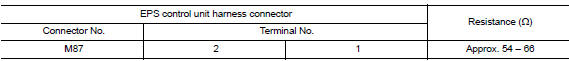
Is the measurement value within the specification? Yes >> go to 3.
No >> repair the eps control unit branch line.
3.Check power supply and ground circuit
Check the power supply and the ground circuit of the EPS control unit. Refer to STC-22, "Diagnosis Procedure".
Is the inspection result normal? YES (Present error)>>Replace the EPS control unit. Refer to STC-39, "Removal and Installation".
YES (Past error)>>Error was detected in the EPS control unit branch line.
NO >> Repair the power supply and the ground circuit.
 Dlc branch line circuit
Diagnosis procedure
1.Check connector
Turn the ignition switch off.
Disconnect the battery cable from the negative terminal.
Check the terminals and connectors of the data link connector for ...
 M&a branch line circuit
Diagnosis procedure
1.Check connector
Turn the ignition switch off.
Disconnect the battery cable from the negative terminal.
Check the terminals and connectors of the combination meter for da ...
Other materials:
Brake pedal
Exploded View
WITHOUT BRAKE PEDAL POSITION SWITCH
Snap pin
Brake pedal assembly
Brake pedal pad
Stop lamp switch
Clip
Clevis pin
Apply multi-purpose grease.
WITH BRAKE PEDAL POSITION SWITCH
Snap pin
Brake pedal assembly
Brake pedal pad
Brake pedal position switch
...
P0603 ECM
DTC Logic
DTC DETECTION LOGIC
DTC No.
CONSULT screen terms
(Trouble diagnosis content)
DTC detecting condition
Possible cause
P0603
ECM BACK UP CIRCUIT
[Internal control module keep
alive memory (KAM) error]
Malfunction in the internal back up RAM o ...
P0743 Torque converter
DTC Logic
DTC DETECTION LOGIC
DTC
CONSULT screen terms
(Trouble diagnosis content)
DTC detection condition
Possible causes
P0743
TORQUE CONVERTER
(Torque Converter Clutch Circuit
Electrical)
The TCM torque converter clutch solenoid
valve current monitor ...
