Nissan Sentra Service Manual: P0743 Torque converter
DTC Logic
DTC DETECTION LOGIC
| DTC | CONSULT screen terms (Trouble diagnosis content) | DTC detection condition | Possible causes |
| P0743 | TORQUE CONVERTER (Torque Converter Clutch Circuit Electrical) | The TCM torque converter clutch solenoid
valve current monitor reading is 200 mA or
less continuously for 480 msec or more under
the following diagnosis conditions: Diagnosis conditions
|
|
DTC CONFIRMATION PROCEDURE
CAUTION:
Be careful of the driving speed.
1.PREPARATION BEFORE OPERATION (PART 1)
If another “DTC CONFIRMATION PROCEDURE” occurs just before, turn ignition switch OFF and wait for at least 10 seconds, then perform the next test.
>> GO TO 2.
2.PREPARATION BEFORE OPERATION (PART 2)
 With CONSULT
- Start the engine.
- Select “Data Monitor” in “TRANSMISSION”.
- Select “FLUID TEMP”.
- Confirm that the CVT fluid temperature is in the following range.
FLUID TEMP : 10В°C (50В°F) or more
 With GST
- Start the engine.
- Set the CVT fluid to 10В°C (50В°F) or more.
NOTE:
When the ambient temperature is 20В°C (68В°F), the CVT fluid usually increases to 50 to 80В°C (122 to 176В°F) with driving in an urban area for approximately 10 minutes.
Is the CVT fluid 10В°C (50В°F) or more? YES >> GO TO 3.
NO >> 1. Warm the transaxle.
2. GO TO 3.
3.CHECK DTC DETECTION
- Drive the vehicle.
- Maintain the following conditions for 5 seconds or more.
Selector lever : “D” position
Vehicle speed : 40 km/h (25 MPH) or more
- Stop the vehicle.
- Check the first trip DTC.
Is “P0743” detected? YES >> Go to TM-187, "Diagnosis Procedure".
NO >> INSPECTION END
Diagnosis Procedure
1.CHECK CIRCUIT BETWEEN TCM AND CVT UNIT
- Turn ignition switch OFF.
- Disconnect TCM connector and CVT unit connector
- Check continuity between TCM harness connector terminal and ground.
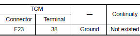
Is the check result normal? YES >> GO TO 2.
NO >> Repair or replace malfunctioning parts.
2.CHECK TORQUE CONVERTER CLUTCH SOLENOID VALVE
Check torque converter clutch solenoid valve. Refer to TM-187, "Component Inspection".
Is the check result normal? YES >> Check intermittent incident. Refer to GI-39, "Intermittent Incident".
NO >> Repair or replace malfunctioning parts.
Component Inspection
1.CHECK TORQUE CONVERTER CLUTCH SOLENOID VALVE
Check resistance between CVT unit connector terminal and ground.
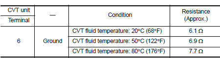 Is the inspection
result normal?
YES >> INSPECTION END
NO >> There is a malfunction of torque converter clutch solenoid valve. Replace transaxle assembly.
Refer to TM-283, "Removal and Installation".
 P0740 Torque converter
DTC Logic
DTC DETECTION LOGIC
DTC
CONSULT screen terms
(Trouble diagnosis content)
DTC detection condition
Possible causes
P0740
TORQUE CONVERTER
(Torque Converter ...
 P0744 Torque converter
DTC Logic
DTC DETECTION LOGIC
DTC
CONSULT screen terms
(Trouble diagnosis content)
DTC detection condition
Possible causes
P0744
TORQUE CONVERTER
(Torque converter ...
Other materials:
Basic inspection
Diagnosis and repair workflow
Work Flow
OVERALL SEQUENCE
DETAILED FLOW
1.OBTAIN INFORMATION ABOUT SYMPTOM
Interview the customer to obtain as much information as possible about the
conditions and environment under
which the malfunction occurred.
>> GO TO 2.
2.CHECK SYMPTOM
...
Precaution
Precaution for Supplemental Restraint System
(SRS) "AIR BAG" and "SEAT BELT PRE-TENSIONER
The Supplemental Restraint System such as “AIR BAG” and “SEAT BELT PRE-TENSIONER”,
used along
with a front seat belt, helps to reduce the risk or severity of injury to th ...
Ecu diagnosis information
Ipdm e/r (intelligent power distribution module engine room)
Reference Value
Values on the diagnosis tool
Terminal layout
Physical values
Fail-safe
Can communication control
When CAN communication with ECM and BCM is impossible, IPDM E/R performs
fail-safe ...
