Nissan Sentra Service Manual: Basic inspection
Diagnosis and repair workflow
Work Flow
OVERALL SEQUENCE
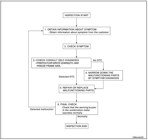
DETAILED FLOW
1.OBTAIN INFORMATION ABOUT SYMPTOM
Interview the customer to obtain as much information as possible about the conditions and environment under which the malfunction occurred.
>> GO TO 2.
2.CHECK SYMPTOM
- Check the symptom based on the information obtained from the customer.
- Check if any other malfunctions are present.
>> GO TO 3.
3.CHECK CONSULT SELF-DIAGNOSIS RESULTS
Connect CONSULT and perform self-diagnosis. Refer to MWI-26, "DTC Index".
Are self-diagnosis results normal? YES >> GO TO 4.
NO >> GO TO 5.
4.NARROW DOWN MALFUNCTIONING PARTS BY SYMPTOM DIAGNOSIS
Perform symptom diagnosis and narrow down the malfunctioning parts.
>> GO TO 5.
5.REPAIR OR REPLACE MALFUNCTIONING PARTS
Repair or replace malfunctioning parts.
NOTE:
If DTC is displayed, erase DTC after repairing or replacing malfunctioning parts.
>> GO TO 6.
6.FINAL CHECK
Check that the warning buzzer in the combination meter operates normally.
Does it operate normally? YES >> Inspection End.
NO >> GO TO 1.
 Wiring diagram
Warning chime system
Wiring diagram
...

Other materials:
CD care and cleaning
Handle a CD by its edges. Do not bend the
disc. Never touch the surface of the disc.
Always place the discs in the storage case
when they are not being used.
To clean a disc, wipe the surface from the
center to the outer edge using a clean, soft
cloth. Do not wipe the disc using ...
Front wiper drive assembly
Exploded view
Wiper blade (RH)
Wiper arm (RH)
Wiper drive assembly
Wiper arm (LH)
Wiper blade (LH)
Removal and installation
REMOVAL
Remove the cowl top. Refer to EXT-26, "Removal and Installation".
Disconnect the harness connector from the wiper drive assembly.
...
Dtc/circuit diagnosis
Malfunction area chart
Main line
Branch line
Short circuit
Main line between ipdm-e and dlc circuit
Diagnosis procedure
1.Check connector
Turn the ignition switch off.
Disconnect the battery cable from the negative terminal.
Check the following terminals and connectors fo ...
