Nissan Sentra Service Manual: Encoder
Driver side
DRIVER SIDE : Description
Detects condition of the front power window motor lh operation and transmits to main power window and door lock/unlock switch as pulse signal.
DRIVER SIDE : Component Function Check
1. Check encoder operation
Check front door glass lh perform auto open/close operation normally with main power window and door lock/unlock switch.
Is the inspection result normal? Yes >> encoder operation is ok.
No >> refer to pwc-50, "driver side : diagnosis procedure".
DRIVER SIDE : Diagnosis Procedure
Regarding wiring diagram information, refer to pwc-18, "wiring diagram".
Encoder circuit check
1. Check encoder operation
- Connect front power window motor lh.
- Turn ignition switch ON.
- Check signal between main power window and door lock/unlock switch connector d5 and ground with oscilloscope.
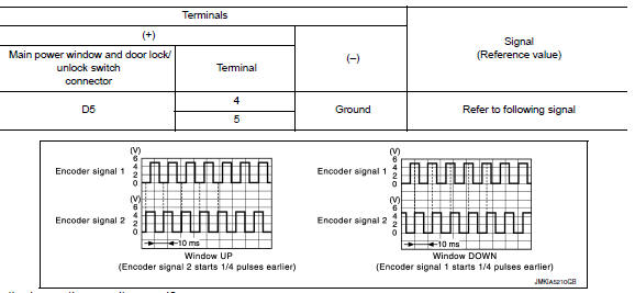
Is the inspection result normal? YES >> Check intermittent incident. Refer to GI-39, "Intermittent Incident".
NO >> GO TO 2.
2. Check front power window motor lh power supply
- Turn ignition switch on.
- Check voltage between front power window motor lh connector d8 and ground.
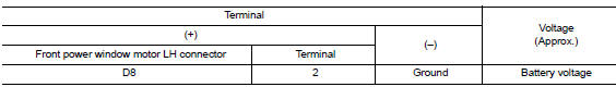
Is the inspection result normal? YES >> GO TO 4.
NO >> GO TO 3.
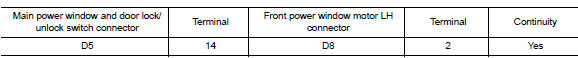
3. Check harness continuity 1
- Turn ignition switch OFF.
- Disconnect main power window and door lock/unlock switch and front power window motor lh.
- Check continuity between main power window and door lock/unlock switch connector D5 and front power window motor connector D8.
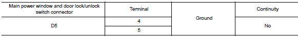
- Check continuity between main power window and door lock/unlock switch connector d5 and ground.

Is the inspection result normal? YES >> Replace main power window and door lock/unlock switch. Refer to PWC-70, "Removal and Installation".
After that, refer to PWC-29, "Work Procedure".
NO >> Repair or replace harness or connectors.
4. Check ground circuit
- Turn ignition switch off.
- Disconnect front power window motor LH.
- Check continuity between front power window motor lh connector d8 and ground.

Is the inspection result normal? Yes >> go to 6.
No >> go to 5.
5. Check harness continuity 2
- Disconnect main power window and door lock/unlock switch.
- Check continuity between main power window and door lock/unlock switch connector d5 and front power window motor lh connector d8.

Is the inspection result normal? YES >> Check main power window and door lock/unlock switch. Refer to PWC-36, "POWER WINDOW MAIN SWITCH : Component Inspection".
NO >> Repair or replace the harness or connectors.
6. Check harness continuity 3
- Disconnect main power window and door lock/unlock switch.
- Check continuity between main power window d5 and door lock/unlock switch connector and front power window motor lh connector d8.
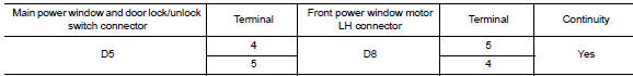
- Check continuity between main power window and door lock/unlock switch connector d5 and ground.
Is the inspection result normal? Yes >> replace front power window motor lh. Refer to gw-16, "removal and installation". After that, refer to pwc-29, "work procedure".
No >> repair or replace harness or connectors.
DRIVER SIDE : Special Repair Requirement
1. Perform initialization procedure
Perform initialization procedure.
Refer to pwc-29, "work procedure".
Is the inspection result normal? Yes >> inspection end.
No >> check intermittent incident. Refer to gi-39, "intermittent incident".
 Power window motor
DRIVER SIDE
DRIVER SIDE : Description
Door glass moves up/down by receiving the signal from main power window and
door lock/unlock switch
DRIVER SIDE : Component Function Check
1. Check front po ...
 Door switch
With intelligent key
WITH INTELLIGENT KEY : Component Function Check
1.Check function
Select DOOR LOCK of BCM using CONSULT.
Select DOOR SW-DR, DOOR SW-AS, DOOR SW-RL and DOOR SW-RR in DATA M ...
Other materials:
P0460 Fuel level sensor
DTC Logic
DTC DETECTION LOGIC
NOTE:
If DTC P0460 is displayed with DTC UXXXX, first perform the trouble
diagnosis for DTC UXXXX.
If DTC P0460 is displayed with DTC P0607, first perform the trouble
diagnosis for DTC P0607. Refer
to EC-350, "DTC Logic".
When the vehicle is ...
Basic inspection
Diagnosis and repair work flow
Work flow
Detailed flow
1.Obtain information about symptom
Interview the customer to obtain as much information as possible about the
conditions and environment under
which the malfunction occurs.
>> GO TO 2.
2.Check symptom
Check the symptom based ...
P0456 EVAP Control system
DTC Logic
DTC DETECTION LOGIC
This diagnosis detects leaks in the EVAP line between fuel tank and EVAP
canister purge volume control solenoid
valve, using the negative pressure caused by decrease of fuel temperature in the
fuel tank after turning
ignition switch OFF.
If ECM judges there a ...
