Nissan Sentra B18 (2020-2025) Service Manual: Ecu Diagnosis Information. Tcm
Tcm
Reference Value
Reference Value
CONSULT DATA MONITOR STANDARD VALUE
-
In CONSULT, electric shift timing or lock-up timing, i.e. operation timing of each solenoid valve, is displayed. Therefore, if there is an obvious difference between the shift timing estimated from a shift shock (or engine speed variations) and that shown on the CONSULT, the mechanism parts (including the hydraulic circuit) excluding the solenoids and sensors may be malfunctioning. In this case, check the mechanical parts following the appropriate diagnosis procedure.
-
Shift point (gear position) displayed on CONSULT slightly differs from shift pattern described in Service Manual. This is due to the following reasons.
-
Actual shift pattern may vary slightly within specified tolerances.
-
While shift pattern described in Service Manual indicates start of each shift, CONSULT shows gear position at end of shift.
-
The solenoid display (ON/OFF) on CONSULT is changed at the start of gear shifting. In contrast, the gear position display is changed at the time when gear shifting calculated in the control unit is completed.
-

The following table includes information (items) inapplicable to this Nissan Sentra vehicle. For information (items) applicable to this vehicle, refer to CONSULT display items.
|
Monitor item |
Condition |
Value/Status (Approx.) |
|---|---|---|
|
MANU MODE SIGNAL |
Always |
Off |
|
Ds mode signal |
In drive sport mode |
On |
|
Other than the above |
Off |
|
|
M GEAR POS |
Always |
1 |
|
2WD/4WD identification |
Ignition switch ON |
2WD/4WD |
|
Range switch 1 status |
Ignition switch ON |
Normal |
|
Range switch 2 status |
Ignition switch ON |
Normal |
|
Range switch 3 status |
Ignition switch ON |
Normal |
|
Range switch 4 status |
Ignition switch ON |
Normal |
|
PRI SPEED SEN |
Ignition switch ON |
Normal |
|
SEC REV SENSOR |
Ignition switch ON |
Normal |
|
INPUT SPEED SENSOR |
Ignition switch ON |
Normal |
|
T/M warning indicator DTC |
Ignition switch ON |
Displays the first DTC when CVT system warning is displayed. |
|
Electric oil pump target speed |
Stop/start system is activated |
940 - 2830 rpm |
|
0 rpm |
|
|
Electric oil pump speed |
Stop/start system is activated |
940 - 2830 rpm |
|
0 rpm |
|
|
IDLE SW |
Accelerator pedal is released |
On |
|
Accelerator pedal is fully depressed |
Off |
|
|
STRDWNSW |
Always |
Off |
|
STRUPSW |
Always |
Off |
|
CVT LAMP |
Always |
Off |
|
VDC ON |
VDC is activated |
On |
|
Other than the above |
Off |
|
|
TCS ON |
TCS is activated |
On |
|
Other than the above |
Off |
|
|
ABS FAIL SIGNAL |
When ABS malfunction signal is received |
On |
|
Other than the above |
Off |
|
|
ABS ON |
ABS is activated |
On |
|
Other than the above |
Off |
|
|
G SEN CALIBRATION |
When G sensor calibration is completed |
DONE |
|
When G sensor calibration is not completed |
YET |
|
|
N IDLE STATUS |
Always |
Off |
|
Back-up lamp relay monitor |
Shift position: R position |
On |
|
Other than the above |
Off |
|
|
Back-up lamp relay instructions |
Shift position: R position |
On |
|
Other than the above |
Off |
|
|
RANGE SW 1 |
Shift position: D and R position |
On |
|
Other than the above |
Off |
|
|
RANGE SW 2 |
Shift position: D position |
On |
|
Other than the above |
Off |
|
|
RANGE SW 3 |
Shift position: R and D position |
On |
|
Other than the above |
Off |
|
|
RANGE SW 4 |
Shift position: R, N, and D position |
On |
|
Other than the above |
Off |
|
|
Electric oil pump temp sensor |
Ignition switch ON |
Normal |
|
Electric oil pump over current |
Ignition switch ON |
Normal |
|
Electric oil pump angle sensor |
Ignition switch ON |
Normal |
|
Electric oil pump low voltage |
Ignition switch ON |
Normal |
|
Electric oil pump over temp |
Ignition switch ON |
Normal |
|
Electric oil pump signal |
Ignition switch ON |
Normal |
|
Electric oil pump over voltage |
Ignition switch ON |
Normal |
|
ENGBRKLVL |
When the engine brake level of ŌĆ£ENGINE BRAKE ADJŌĆØ. in ŌĆ£Work SupportŌĆØ is ON |
On |
|
When the engine brake level of ŌĆ£ENGINE BRAKE ADJŌĆØ. in ŌĆ£Work SupportŌĆØ is OFF |
Off |
|
|
CVTF DETERIORATION DATE* |
ŌĆö |
ŌĆö |
|
GAIN LU |
ŌĆö |
ŌĆö |
|
OFFSET LU |
ŌĆö |
ŌĆö |
|
MAP NO LU |
ŌĆö |
ŌĆö |
|
OFFSET2 LU |
ŌĆö |
ŌĆö |
|
GAIN PL |
ŌĆö |
ŌĆö |
|
OFFSET PL |
ŌĆö |
ŌĆö |
|
MAP NO PL |
ŌĆö |
ŌĆö |
|
OFFSET2 PL |
ŌĆö |
ŌĆö |
|
GAIN PRI |
ŌĆö |
ŌĆö |
|
OFFSET PRI |
ŌĆö |
ŌĆö |
|
MAP NO PRI |
ŌĆö |
ŌĆö |
|
OFFSET2 PRI |
ŌĆö |
ŌĆö |
|
Secondary calibration gain |
ŌĆö |
ŌĆö |
|
Secondary calibration offset |
ŌĆö |
ŌĆö |
|
Secondary calibration map No. |
ŌĆö |
ŌĆö |
|
Secondary calibration offset 2 |
ŌĆö |
ŌĆö |
|
GAIN L/B |
ŌĆö |
ŌĆö |
|
OFFSET L/B |
ŌĆö |
ŌĆö |
|
MAP NO L/B |
ŌĆö |
ŌĆö |
|
OFFSET2 L/B |
ŌĆö |
ŌĆö |
|
INIT OFFSET LB C |
ŌĆö |
ŌĆö |
|
INIT OFFSET LB D |
ŌĆö |
ŌĆö |
|
INIT OFFSET LB E |
ŌĆö |
ŌĆö |
|
INIT OFFSET LB F |
ŌĆö |
ŌĆö |
|
INIT OFFSET SLCT E |
ŌĆö |
ŌĆö |
|
INIT OFFSET SLCT F |
ŌĆö |
ŌĆö |
|
INIT OFFSET SLCT G |
ŌĆö |
ŌĆö |
|
INIT OFFSET H/R A |
ŌĆö |
ŌĆö |
|
INIT OFFSET H/R B |
ŌĆö |
ŌĆö |
|
INIT OFFSET H/R C |
ŌĆö |
ŌĆö |
|
INIT OFFSET H/R D |
ŌĆö |
ŌĆö |
|
INIT OFFSET H/R E |
ŌĆö |
ŌĆö |
|
INIT OFFSET H/R F |
ŌĆö |
ŌĆö |
|
INIT OFFSET LB A |
ŌĆö |
ŌĆö |
|
INIT OFFSET LB B |
ŌĆö |
ŌĆö |
|
Lock-up extraolated value 1.1 |
ŌĆö |
ŌĆö |
|
Lock-up extraolated value 1.2 |
ŌĆö |
ŌĆö |
|
Lock-up extraolated version |
ŌĆö |
ŌĆö |
|
Control valve Identification ID |
ŌĆö |
ŌĆö |
|
Calibration version |
ŌĆö |
ŌĆö |
|
ID 1 |
ŌĆö |
ŌĆö |
|
ID 2 |
ŌĆö |
ŌĆö |
|
Control valve part number 1 |
ŌĆö |
ŌĆö |
|
Control valve part number 2 |
ŌĆö |
ŌĆö |
|
Control valve part number 3 |
ŌĆö |
ŌĆö |
|
Control valve part number 4 |
ŌĆö |
ŌĆö |
|
Control valve part number 5 |
ŌĆö |
ŌĆö |
|
Control valve part number 6 |
ŌĆö |
ŌĆö |
|
Control valve part number 7 |
ŌĆö |
ŌĆö |
|
Control valve part number 8 |
ŌĆö |
ŌĆö |
|
Control valve production year |
ŌĆö |
ŌĆö |
|
C/V production line code |
ŌĆö |
ŌĆö |
|
C/V production month |
ŌĆö |
ŌĆö |
|
Control valve serialnumber 1 |
ŌĆö |
ŌĆö |
|
Control valve serialnumber 2 |
ŌĆö |
ŌĆö |
|
Control valve serialnumber 3 |
ŌĆö |
ŌĆö |
|
Control valve serialnumber 4 |
ŌĆö |
ŌĆö |
|
Control valve serialnumber 5 |
ŌĆö |
ŌĆö |
|
Control valve serialnumber 6 |
ŌĆö |
ŌĆö |
|
C/V model information |
ŌĆö |
ŌĆö |
|
SLCT INITIALIZE LEARN |
ŌĆö |
ŌĆö |
|
LU INITIALIZE LEARN |
ŌĆö |
ŌĆö |
|
SLCT INITIALIZE TEMP |
ŌĆö |
ŌĆö |
|
LU INITIALIZE TEMP |
ŌĆö |
ŌĆö |
|
SLCT INITIALIZE ND PRS |
ŌĆö |
ŌĆö |
|
SLCT INITIALIZE ND TIME |
ŌĆö |
ŌĆö |
|
SLCT INITIALIZE NR PRS |
ŌĆö |
ŌĆö |
|
SLCT INITIALIZE NR TIME |
ŌĆö |
ŌĆö |
|
LU INITIALIZE LEARN 1 |
ŌĆö |
ŌĆö |
|
LU INITIALIZE LEARN 2 |
ŌĆö |
ŌĆö |
|
Clearance No. |
ŌĆö |
ŌĆö |
|
Unit manufacturing date 1 |
ŌĆö |
ŌĆö |
|
Unit manufacturing date 2 |
ŌĆö |
ŌĆö |
|
Unit manufacturing date 3 |
ŌĆö |
ŌĆö |
|
Unit manufacturing date 4 |
ŌĆö |
ŌĆö |
|
Unit manufacturing date 5 |
ŌĆö |
ŌĆö |
|
Unit manufacturing date 6 |
ŌĆö |
ŌĆö |
|
Unit part number 1 |
ŌĆö |
ŌĆö |
|
Unit part number 2 |
ŌĆö |
ŌĆö |
|
Unit part number 3 |
ŌĆö |
ŌĆö |
|
Unit part number 4 |
ŌĆö |
ŌĆö |
|
Unit part number 5 |
ŌĆö |
ŌĆö |
|
Unit part number 6 |
ŌĆö |
ŌĆö |
|
Unit part number 7 |
ŌĆö |
ŌĆö |
|
Unit part number 8 |
ŌĆö |
ŌĆö |
|
Unit production year |
ŌĆö |
ŌĆö |
|
Unit production line code |
ŌĆö |
ŌĆö |
|
Unit production month |
ŌĆö |
ŌĆö |
|
Unit serial number 1 |
ŌĆö |
ŌĆö |
|
Unit serial number 2 |
ŌĆö |
ŌĆö |
|
Unit serial number 3 |
ŌĆö |
ŌĆö |
|
Unit serial number 4 |
ŌĆö |
ŌĆö |
|
Unit serial number 5 |
ŌĆö |
ŌĆö |
|
Unit serial number 6 |
ŌĆö |
ŌĆö |
|
Unit model Information |
ŌĆö |
ŌĆö |
|
VSP SENSOR |
While driving |
Almost same as the speedometer display. |
|
SLIP REV |
While driving |
Engine speed ŌłÆ Input speed |
|
Line pressure |
|
1.6 Mpa |
|
Line pressure sensor |
|
1.57 V |
|
G sensor (TCM) |
Always |
0 V |
|
BRAKESW |
Brake pedal is depressed |
On |
|
Brake pedal is released |
Off |
|
|
SHIFT IND SIGNAL |
When the selector lever is positioned in between each position. |
Off |
|
Shift position: P position |
P |
|
|
Shift position: R position |
R |
|
|
Shift position: N position |
N |
|
|
Shift position: D position |
D |
|
|
Manual mode: 1st |
M1 |
|
|
Manual mode: 2nd |
M2 |
|
|
Manual mode: 3rd |
M3 |
|
|
Manual mode: 4th |
M4 |
|
|
Manual mode: 5th |
M5 |
|
|
Manual mode: 6th |
M6 |
|
|
Manual mode: 7th |
M7 |
|
|
Manual mode: 8th |
M8 |
|
|
RANGE |
Shift position: P and N positions |
N/P |
|
Shift position: R position |
R |
|
|
Shift position: D position |
D |
|
|
Shift position: M position |
||
|
ESTM VSP SIG |
While driving |
Almost same as the speedometer display. |
|
VIGN SEN |
Ignition switch: ON |
10.0 ŌĆō 16.0 V |
|
PVIGN VOLT |
Ignition switch: ON |
10.0 ŌĆō 16.0 V |
|
Nissan Sentra Vehicle SPEED |
While driving |
Almost same as the speedometer display. |
|
INPUT REV |
In driving (lock-up ON) |
Almost same as the engine speed. |
|
PRI SPEED |
In driving (lock-up ON) |
Approximately matches the engine speed. |
|
SEC SPEED |
While driving |
PRI SPEED ├Ę PULLEY GEAR RATIO |
|
ENG SPEED |
Engine running |
Almost same reading as tachometer |
|
PULLEY GEAR RATIO |
In driving (forward) |
2.805-0.357 |
|
In driving (reverse) |
2.09 |
|
|
G SPEED |
Nissan Sentra Vehicle stopped |
0 G |
|
ACCEL POSI SEN 1 |
Accelerator pedal released |
0 deg |
|
VENG TRQ |
While driving |
The value changes along with acceleration/deceleration. |
|
PRI TRQ |
While driving |
The value changes along with acceleration/deceleration. |
|
SEC PRESSURE |
|
1.43 MPa |
|
PRI PRESSURE |
|
0.69MPa |
|
FLUID TEMP |
Ignition switch ON |
Displays the CVT fluid temperature. |
|
DSR REV |
While driving |
It varies along with the driving condition. |
|
TRGT GEAR RATIO |
In driving (forward) |
2.805-0.357 |
|
In driving (reverse) |
2.09 |
|
|
LU PRS |
|
-0.2 MPa |
|
0.35MPa |
|
|
LINE PRS |
|
1.6 MPa |
|
TRGT PRI PRESSURE |
|
0.69MPa |
|
Target select pressure |
|
0.000 MPa |
|
TARGET SEC PRESSUR |
|
1.43 MPa |
|
ISOLT1 |
ŌĆö |
ŌĆö |
|
ISOLT2 |
ŌĆö |
ŌĆö |
|
PRI SOLENOID |
ŌĆö |
ŌĆö |
|
SEC SOLENOID CURRENT |
ŌĆö |
ŌĆö |
|
SELECT SOLENOID CURRENT |
ŌĆö |
ŌĆö |
|
SOLMON1 |
ŌĆö |
ŌĆö |
|
SOLMON2 |
ŌĆö |
ŌĆö |
|
PRI SOL MON |
ŌĆö |
ŌĆö |
|
SEC SOL MON CURRENT |
ŌĆö |
ŌĆö |
|
SELECT SOL MON CURRENT |
ŌĆö |
ŌĆö |
|
G SEN SLOPE |
Flat road |
0% |
|
Uphill gradient |
The value changes to the positive sidealong with uphill gradient. (Maximum40.45%) |
|
|
Downhill gradient |
The value changes to the negative sidealong with downhill gradient. (Minimum ŌłÆ40.45%) |
|
|
CVT-B |
ŌĆö |
ŌĆö |
|
CVT-A |
ŌĆö |
ŌĆö |
|
Slip revolution absolute value |
ŌĆö |
ŌĆö |
|
Target transmission speed |
ŌĆö |
ŌĆö |
|
Input speed sensor |
In driving (lock-up ON) |
Approximately matches the engine speed. |
|
PRI SPEED SEN |
In driving (lock-up ON) |
Approximately matches the engine speed. |
|
SEC REV SENSOR |
While driving |
PRI SPEED ├Ę PULLEY GEAR RATIO |
|
ENG SPEED SIG |
Engine running |
Almost same reading as tachometer |
|
SEC PRESSURE SEN |
|
1.45V |
|
PRI PRESSURE SEN |
|
0.96V |
|
ATF TEMP SEN |
CVT fluid: Approx. 20┬░C (68┬░F) |
2.01 ŌĆō 2.05 V |
|
CVT fluid: Approx. 50┬░C (122┬░F) |
1.45 ŌĆō 1.50 V |
|
|
CVT fluid: Approx. 80┬░C (176┬░F) |
0.90 ŌĆō 0.94 V |
|
|
G SENSOR |
|
0 G |
|
TRQ RTO |
While driving |
The value changes along with acceleration/deceleration. |
*: These monitor items do not use.
TERMINAL LAYOUT

INPUT/OUTPUT SIGNAL STANDARD
|
Terminal No. (Wire color) |
Description |
Condition |
Value (Approx.) |
|||
|---|---|---|---|---|---|---|
|
+ |
ŌłÆ |
Signal |
Input/Output |
|||
|
4 (P) |
Ground |
Transmission range switch 1 |
Input |
Ignition switch ON |
Selector lever: ŌĆ£RŌĆØ, ŌĆ£NŌĆØ or ŌĆ£DŌĆØ position |
5 V |
|
Other than the above |
0 V |
|||||
|
5 (SB) |
Ground |
Transmission range switch 2 |
Input |
Selector lever: ŌĆ£NŌĆØ, ŌĆ£DŌĆØ or ŌĆ£LŌĆØ position |
5 V |
|
|
Other than the above |
0 V |
|||||
|
6 (Y) |
Ground |
Transmission range switch 3 |
Input |
Selector lever: ŌĆ£DŌĆØ or ŌĆ£LŌĆØ position |
5 V |
|
|
Other than the above |
0 V |
|||||
|
7 (GR) |
Ground |
Transmission range switch 4 |
Input |
Selector lever: ŌĆ£RŌĆØ or ŌĆ£DŌĆØ position |
5 V |
|
|
Other than the above |
0 V |
|||||
|
8 (GR) |
ŌĆö |
CAN2-H |
Input/Output |
ŌĆö |
ŌĆö |
|
|
9 (R) |
ŌĆö |
CAN2-L |
Input/Output |
ŌĆö |
ŌĆö |
|
|
11 (B) |
Ground |
Sensor ground |
ŌĆö |
Always |
0 V |
|
|
12 (BR) |
Ground |
CVT fluid temperature sensor |
Input |
Ignition switch ON |
CVT fluid: Approx. 20┬░C (68┬░F) |
2.01 ŌĆō 2.05 V |
|
CVT fluid: Approx. 50┬░C (122┬░F) |
1.45 ŌĆō 1.50 V |
|||||
|
CVT fluid: Approx. 80┬░C 176┬░F) |
0.90 ŌĆō 0.94 V |
|||||
|
15 (LG) |
Ground |
Sensor ground |
ŌĆö |
Always |
0 V |
|
|
16 (W) |
Ground |
Secondary pressure sensor |
Input |
|
1.512 V |
|
|
17 (R) |
Ground |
Primary pressure sensor |
Input |
|
0.867 V |
|
|
18 (R) |
Ground |
Line pressure sensor |
Input |
|
1.629 V |
|
|
23 (P) |
ŌĆö |
CAN-L |
Input/Output |
ŌĆö |
ŌĆö |
|
|
24 (LG) |
Ground |
Input speed sensor |
Input |
|
1050 Hz 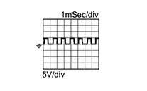
|
|
|
26 (SB) |
Ground |
Sensor power supply |
Output |
Ignition switch: ON |
5.0 V |
|
|
Ignition switch: OFF |
0 V |
|||||
|
29 (P) |
Ground |
Back-up lamp relay |
Output |
Ignition switch ON |
Shift position: ŌĆ£RŌĆØ position |
0 V |
|
Shift position:ŌĆ£PŌĆØ, ŌĆ£NŌĆØ or ŌĆ£DŌĆØ position |
10 ŌłÆ 16 V |
|||||
|
30 (GR) |
Ground |
Line pressure solenoid valve |
Output |
|
 |
|
|
 |
|||||
|
31 (G) |
Ground |
CAN3-H (Electric oil pump) |
Input/ Output |
ŌĆö |
ŌĆö |
|
|
32 (L) |
Ground |
CAN3-L (Electric oil pump) |
Input/ Output |
ŌĆö |
ŌĆö |
|
|
33 (L) |
ŌĆö |
CAN-H |
Input/Output |
ŌĆö |
ŌĆö |
|
|
34 (W) |
Ground |
Output speed sensor |
Input |
|
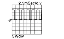
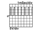
600 Hz 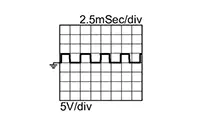
|
|
|
35 (GR) |
Ground |
Primary speed sensor |
Input |
|
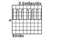
1050 Hz 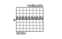
|
|
|
36 (BG) |
Ground |
Sensor power supply |
Output |
Ignition switch: ON |
5.0 V |
|
|
Ignition switch: OFF |
0 V |
|||||
|
37 (Y) |
Ground |
Select solenoid valve |
Output |
|
|
|
|
38 (V) |
Ground |
Torque converter clutch solenoid valve |
Output |
|
 |
|
|
 |
|||||
|
39 (W) |
Ground |
Secondary pressure solenoid valve |
Output |
|
|
|
|
40 (V) |
Ground |
Primary pressure solenoid valve |
Output |
|
|
|
|
41 (B) |
Ground |
Ground |
ŌĆö |
Always |
0 V |
|
|
42 (B) |
Ground |
Ground |
ŌĆö |
Always |
0 V |
|
|
43 (GR) |
Ground |
Solenoid ground |
ŌĆö |
Always |
0 V |
|
|
44 (GR) |
Ground |
Solenoid ground |
ŌĆö |
Always |
0 V |
|
|
45 (P) |
Ground |
Battery power supply |
Input |
Always |
10-16 V |
|
|
46 (P) |
Ground |
Battery power supply |
Input |
Always |
10 ŌłÆ 16 V |
|
|
47 (BR) |
Ground |
Ignition power supply |
Input |
Ignition switch: ON |
10 ŌłÆ 16 V |
|
|
Ignition switch: OFF |
0 V |
|||||
|
48 (BR) |
Ground |
Ignition power supply |
Input |
Ignition switch: ON |
10 ŌłÆ 16 V |
|
|
Ignition switch: OFF |
0 V |
|||||
Fail-Safe
Fail-safe
Refer to Fail-safe.
Protection Control
Protection Control
Refer to Protection Control.
Dtc Inspection Priority Chart
DTC Inspection Priority Chart
If multiple malfunction codes are detected at the same time, check each code according to the DTC check priority list below.
|
Priority |
DTC |
Items (CONSULT screen terms) |
Reference |
|
|---|---|---|---|---|
|
1 |
P0863 |
00 |
CONTROL UNIT(CAN) |
DTC Description |
|
U0073 |
00 |
COMM BUS A OFF |
DTC Description |
|
|
U007A |
00 |
Control module comm Bus H Off |
DTC Description |
|
|
U0100 |
00 |
LOST COMM (ECM) A |
DTC Description |
|
|
U0115 |
00 |
LOST COMM (ECM/PCM B) |
DTC Description |
|
|
U0122 |
00 |
LOST COMM (BRAKE C/U) |
DTC Description |
|
|
U0140 |
00 |
LOST COMM (BCM) |
DTC Description |
|
|
U0287 |
00 |
LOST COMM (T/M FLUID PUMP A) |
DTC Description |
|
|
U0300 |
00 |
CAN COMM DATA |
DTC Description |
|
|
U1112 |
24 |
DECELERATION REQUEST SIGNAL |
DTC Description | |
|
U2140 |
87 |
CAN comm err (ECM) |
DTC Description |
|
|
U2148 |
87 |
CAN comm err (brake control unit) |
DTC Description |
|
|
U214F |
87 |
CAN comm err (BCM) |
DTC Description |
|
|
U2153 |
87 |
CAN comm err (HVAC) |
DTC Description |
|
|
U215B |
87 |
CAN comm err (IPDM E/R) |
DTC Description |
|
|
U2240 |
87 |
CAN comm err (ECM) |
DTC Description |
|
|
U2252 |
87 |
CAN comm err (ADAS control unit) |
DTC Description |
|
|
U2276 |
87 |
CAN comm err (CCM/ST angle sensor) |
DTC Description |
|
|
2 |
P0740 |
00 |
TORQUE CONVERTER |
DTC Description |
|
P0742 |
00 |
TORQUE CONVERTER CLUTCH |
DTC Description |
|
|
P0960 |
00 |
PC SOLENOID A |
DTC Description |
|
|
P0962 |
00 |
PC SOLENOID A |
DTC Description |
|
|
P0963 |
00 |
PC SOLENOID A |
DTC Description |
|
|
P0964 |
00 |
PC SOLENOID B |
DTC Description |
|
|
P0966 |
00 |
PRIMARY PRESSURE SOL |
DTC Description |
|
|
P0967 |
00 |
PRIMARY PRESSURE SOL |
DTC Description |
|
|
P0968 |
00 |
PRESSURE CONTROL SOLENOID C |
DTC Description |
|
|
P0970 |
00 |
PRESSURE CONTROL SOLENOID C |
DTC Description |
|
|
P0971 |
00 |
PRESSURE CONTROL SOLENOID C |
DTC Description |
|
|
P2769 |
00 |
TORQUE CONVERTER |
DTC Description |
|
|
P2770 |
00 |
TORQUE CONVERTER |
DTC Description |
|
|
P2812 |
00 |
PC SOLENOID G |
DTC Description |
|
|
P2814 |
00 |
SELECT SOLENOID |
DTC Description |
|
|
P2815 |
00 |
SELECT SOLENOID |
DTC Description |
|
|
3 |
P0604 |
00 |
CONTROL MODULE RAM |
DTC Description |
|
P0605 |
00 |
CONTROL MODULE ROM |
DTC Description |
|
|
P0606 |
00 |
CONTROL MODULE |
DTC Description |
|
|
P060A |
00 |
CONTROL MODULE |
DTC Description |
|
|
P062F |
00 |
EEPROM |
DTC Description |
|
|
P0705 |
00 |
T/M RANGE SENSOR A |
DTC Description |
|
|
P0706 |
00 |
T/M RANGE SENSOR A |
DTC Description |
|
|
P0711 |
00 |
FLUID TEMP SENSOR A |
DTC Description |
|
|
P0712 |
00 |
FLUID TEMP SENSOR A |
DTC Description |
|
|
P0713 |
00 |
FLUID TEMP SENSOR A |
DTC Description |
|
|
P0715 |
00 |
INPUT SPEED SENSOR A |
DTC Description |
|
|
P0716 |
00 |
INPUT SPEED SENSOR A |
DTC Description |
|
|
P0717 |
00 |
INPUT SPEED SENSOR A |
DTC Description |
|
|
P0718 |
00 |
Input/Turbine speed sensor A |
DTC Description |
|
|
P0791 |
00 |
INTERMEDIATE SPEED SENSOR A |
DTC Description |
|
|
P0792 |
00 |
INTERMEDIATE SPEED SENSOR A |
DTC Description |
|
|
P0793 |
00 |
INTERMEDIATE SPEED SENSOR A |
DTC Description |
|
|
P0794 |
00 |
INTERMEDIATE SPEED SENSOR A |
DTC Description |
|
|
P07BF |
00 |
INPUT SPEED SENSOR A |
DTC Description |
|
|
P07C0 |
00 |
INPUT SPEED SENSOR A |
DTC Description |
|
|
P07C1 |
00 |
INPUT SPEED SENSOR B |
DTC Description |
|
|
P07C2 |
00 |
INPUT SPEED SENSOR B |
DTC Description |
|
|
P07C5 |
00 |
INTERMEDIATE SPEED SENSOR A |
DTC Description |
|
|
P07C6 |
00 |
INTERMEDIATE SPEED SENSOR A |
DTC Description |
|
|
P0845 |
00 |
FLUID PRESS SEN/SW A |
DTC Description |
|
|
P0846 |
00 |
FLUID PRESS SEN/SW B |
DTC Description |
|
|
P0847 |
00 |
FLUID PRESS SEN/SW B |
DTC Description |
|
|
P0848 |
00 |
FLUID PRESS SEN/SW B |
DTC Description |
|
|
P084A |
00 |
FLUID PRESSURE SEN/SW H |
DTC Description |
|
|
P084B |
00 |
FLUID PRESSURE SEN/SW H |
DTC Description |
|
|
P084C |
00 |
FLUID PRESS SEN/SW H |
DTC Description |
|
|
P084D |
00 |
FLUID PRESS SEN/SW H |
DTC Description |
|
|
P0870 |
00 |
FLUID PRESS SEN/SW A |
DTC Description |
|
|
P0871 |
00 |
FLUID PRESSURE SEN/SW C |
DTC Description |
|
|
P0872 |
00 |
T/M fluid press sensor/switch c |
DTC Description |
|
|
P0873 |
00 |
FLUID PRESSURE SEN/SW C |
DTC Description |
|
|
P0890 |
00 |
TCM |
DTC Description |
|
|
P1588 |
00 |
G SENSOR |
DTC Description |
|
|
P159C |
00 |
G SENSOR |
DTC Description |
|
|
P159D |
00 |
G SENSOR |
DTC Description |
|
|
P188E |
00 |
ELECTRIC OIL PUMP |
DTC Description |
|
|
P1AE0 |
61 |
Range misdisplay |
DTC Description | |
|
P2765 |
00 |
INPUT SPEED SENSOR B |
DTC Description |
|
|
P2766 |
00 |
INPUT SPEED SENSOR B |
DTC Description |
|
|
P2767 |
00 |
INPUT SPEED SENSOR B |
DTC Description |
|
|
P2768 |
00 |
Input/Turbine speed sensor B |
DTC Description |
|
|
P27B3 |
00 |
CONTROL MODULE |
DTC Description |
|
|
P27B5 |
00 |
CONTROL MODULE |
DTC Description |
|
|
P27EB |
00 |
T/M RANGE CTRL A POSI SEN/SW |
DTC Description |
|
|
P27EC |
00 |
T/M RANGE CTRL A POSI SEN/SW |
DTC Description |
|
|
P27EF |
00 |
T/M RANGE CTRL B POSI SEN/SW |
DTC Description |
|
|
P27F0 |
00 |
T/M RANGE CTRL B POSI SEN/SW |
DTC Description |
|
|
4 |
P0741 |
00 |
TORQUE CONVERTER |
DTC Description |
|
P0746 |
00 |
PC SOLENOID A |
DTC Description |
|
|
P0747 |
00 |
PRESSURE CONTROL SOLENOID A |
DTC Description |
|
|
P0776 |
00 |
PRESSURE CONTROL SOLENOID B |
DTC Description |
|
|
P0777 |
00 |
PRESSURE CONTROL SOLENOID B |
DTC Description |
|
|
P0796 |
00 |
PRESSURE CONTROL SOLENOID C |
DTC Description |
|
|
P0797 |
00 |
PRESSURE CONTROL SOLENOID C |
DTC Description |
|
|
P0961 |
00 |
PC SOLENOID A |
DTC Description |
|
|
P17F0 |
07 |
CVT JUDDER (T/M INSPECTION) |
DTC Description | |
|
P17F1 |
07 |
CVT JUDDER (C/V INSPECTION) |
DTC Description | |
|
P17F2 |
07 |
CVT JUDDER (T/C INSPECTION) |
DTC Description | |
|
P187E |
09 |
T/M SYSTEM MALFUNCTION |
DTC Description |
|
|
P271E |
00 |
WHEEL TORQUE CALCULATION SIGNAL |
DTC Description |
|
|
P27A1 |
00 |
EL/AUX T/M FLUID PUMP A |
DTC Description |
|
|
P27A3 |
00 |
EL/AUX T/M FLUID PUMP B |
DTC Description |
|
|
P27A4 |
00 |
EL/AUX T/M FLUID PUMP B |
DTC Description |
|
|
P27A6 |
00 |
EL/AUX T/M FLUID PUMP B |
DTC Description |
|
|
P2808 |
00 |
PRESSURE CONTROL SOLENOID G |
DTC Description |
|
|
P2809 |
00 |
PRESSURE CONTROL SOLENOID G |
DTC Description |
|
|
P28ED |
00 |
EL/AUX T/M FLUID PUMP B |
DTC Description |
|
|
P28EE |
00 |
EL/AUX T/M FLUID PUMP B |
DTC Description |
|
Dtc Index
DTC Index
Note:
-
If multiple malfunction codes are detected at the same time, check each code according to the ŌĆ£DTC check priority listŌĆØ. DTC Inspection Priority Chart.
-
The ignition counter is displayed in ŌĆ£FFDŌĆØ. Refer to CONSULT Function.
Self Diagnostic Result
├Ś:Applicable ŌĆö: Not applicable|
DTC*1, *2 |
Items (CONSULT screen terms) |
Trip |
MIL *3 |
CVT system warning *4 |
Reference |
||
|---|---|---|---|---|---|---|---|
|
GST |
CONSULT (TRANSMISSION) |
||||||
|
P0604 |
P0604 |
00 |
CONTROL MODULE RAM |
1 |
├Ś |
C |
DTC Description |
|
P0605 |
P0605 |
00 |
CONTROL MODULE ROM |
1 |
├Ś |
C |
DTC Description |
|
P0606 |
P0606 |
00 |
CONTROL MODULE |
1 |
├Ś |
C |
DTC Description |
|
P060A |
P060A |
00 |
CONTROL MODULE |
1 |
├Ś |
C |
DTC Description |
|
P062F |
P062F |
00 |
EEPROM |
1 |
├Ś |
A |
DTC Description |
|
P0705 |
P0705 |
00 |
T/M RANGE SENSOR A |
2 |
├Ś |
C |
DTC Description |
|
P0706 |
P0706 |
00 |
T/M RANGE SENSOR A |
2 |
├Ś |
C |
DTC Description |
|
P0711 |
P0711 |
00 |
FLUID TEMP SENSOR A |
2 |
├Ś |
C |
DTC Description |
|
P0712 |
P0712 |
00 |
FLUID TEMP SENSOR A |
2 |
├Ś |
C |
DTC Description |
|
P0713 |
P0713 |
00 |
FLUID TEMP SENSOR A |
2 |
├Ś |
C |
DTC Description |
|
P0715 |
P0715 |
00 |
INPUT SPEED SENSOR A |
2 |
├Ś |
C |
DTC Description |
|
P0716 |
P0716 |
00 |
INPUT SPEED SENSOR A |
2 |
├Ś |
C |
DTC Description |
|
P0717 |
P0717 |
00 |
INPUT SPEED SENSOR A |
2 |
├Ś |
C |
DTC Description |
|
P0718 |
P0718 |
00 |
Input/Turbine speed sensor A |
2 |
├Ś |
A |
DTC Description |
|
P0740 |
P0740 |
00 |
TORQUE CONVERTER |
2 |
├Ś |
C |
DTC Description |
|
P0741 |
P0741 |
00 |
TORQUE CONVERTER |
2 |
├Ś |
C |
DTC Description |
|
P0742 |
P0742 |
00 |
TORQUE CONVERTER CLUTCH |
1 |
├Ś |
B:Running A:Stopping |
DTC Description |
|
P0746 |
P0746 |
00 |
PC SOLENOID A |
2 |
├Ś |
C |
DTC Description |
|
P0747 |
P0747 |
00 |
PRESSURE CONTROL SOLENOID A |
2 |
├Ś |
C |
DTC Description |
|
P0776 |
P0776 |
00 |
PRESSURE CONTROL SOLENOID B |
2 |
├Ś |
C |
DTC Description |
|
P0777 |
P0777 |
00 |
PRESSURE CONTROL SOLENOID B |
2 |
├Ś |
C |
DTC Description |
|
P0791 |
P0791 |
00 |
INTERMEDIATE SPEED SENSOR A |
2 |
├Ś |
C |
DTC Description |
|
P0792 |
P0792 |
00 |
INTERMEDIATE SPEED SENSOR A |
2 |
├Ś |
C |
DTC Description |
|
P0793 |
P0793 |
00 |
INTERMEDIATE SPEED SENSOR A |
2 |
├Ś |
C |
DTC Description |
|
P0794 |
P0794 |
00 |
INTERMEDIATE SPEED SENSOR A |
2 |
├Ś |
A |
DTC Description |
|
P0796 |
P0796 |
00 |
PRESSURE CONTROL SOLENOID C |
2 |
├Ś |
C |
DTC Description |
|
P0797 |
P0797 |
00 |
PRESSURE CONTROL SOLENOID C |
2 |
├Ś |
C |
DTC Description |
|
P07BF |
P07BF |
00 |
INPUT SPEED SENSOR A |
2 |
├Ś |
C |
DTC Description |
|
P07C0 |
P07C0 |
00 |
INPUT SPEED SENSOR A |
2 |
├Ś |
C |
DTC Description |
|
P07C1 |
P07C1 |
00 |
INPUT SPEED SENSOR B |
2 |
├Ś |
C |
DTC Description |
|
P07C2 |
P07C2 |
00 |
INPUT SPEED SENSOR B |
2 |
├Ś |
C |
DTC Description |
|
P07C5 |
P07C5 |
00 |
INTERMEDIATE SPEED SENSOR A |
2 |
├Ś |
C |
DTC Description |
|
P07C6 |
P07C6 |
00 |
INTERMEDIATE SPEED SENSOR A |
2 |
├Ś |
C |
DTC Description |
|
P0845 |
P0845 |
00 |
FLUID PRESS SEN/SW A |
2 |
├Ś |
A |
DTC Description |
|
P0846 |
P0846 |
00 |
FLUID PRESS SEN/SW B |
2 |
├Ś |
A |
DTC Description |
|
P0847 |
P0847 |
00 |
FLUID PRESS SEN/SW B |
2 |
├Ś |
A |
DTC Description |
|
P0848 |
P0848 |
00 |
FLUID PRESS SEN/SW B |
2 |
├Ś |
A |
DTC Description |
|
P084A |
P084A |
00 |
FLUID PRESSURE SEN/SW H |
2 |
├Ś |
A |
DTC Description |
|
P084B |
P084B |
00 |
FLUID PRESSURE SEN/SW H |
2 |
├Ś |
A |
DTC Description |
|
P084C |
P084C |
00 |
FLUID PRESS SEN/SW H |
2 |
├Ś |
A |
DTC Description |
|
P084D |
P084D |
00 |
FLUID PRESS SEN/SW H |
2 |
├Ś |
A |
DTC Description |
|
P0863 |
P0863 |
00 |
CONTROL UNIT(CAN) |
1 |
├Ś |
C |
DTC Description |
|
P0870 |
P0870 |
00 |
FLUID PRESS SEN/SW A |
2 |
├Ś |
A |
DTC Description |
|
P0871 |
P0871 |
00 |
FLUID PRESSURE SEN/SW C |
2 |
├Ś |
A |
DTC Description |
|
P0872 |
P0872 |
00 |
T/M fluid press sensor/switch c |
2 |
├Ś |
A |
DTC Description |
|
P0873 |
P0873 |
00 |
FLUID PRESSURE SEN/SW C |
2 |
├Ś |
A |
DTC Description |
|
P0890 |
P0890 |
00 |
TCM |
1 |
├Ś |
C |
DTC Description |
|
P0960 |
P0960 |
00 |
PC SOLENOID A |
2 |
├Ś |
C |
DTC Description |
|
P0961 |
P0961 |
00 |
PC SOLENOID A |
2 |
├Ś |
C |
DTC Description |
|
P0962 |
P0962 |
00 |
PC SOLENOID A |
2 |
├Ś |
C |
DTC Description |
|
P0963 |
P0963 |
00 |
PC SOLENOID A |
2 |
├Ś |
C |
DTC Description |
|
P0964 |
P0964 |
00 |
PC SOLENOID B |
2 |
├Ś |
C |
DTC Description |
|
P0966 |
P0966 |
00 |
PRIMARY PRESSURE SOL |
2 |
├Ś |
C |
DTC Description |
|
P0967 |
P0967 |
00 |
PRIMARY PRESSURE SOL |
2 |
├Ś |
C |
DTC Description |
|
P0968 |
P0968 |
00 |
PRESSURE CONTROL SOLENOID C |
2 |
├Ś |
C |
DTC Description |
|
P0970 |
P0970 |
00 |
PRESSURE CONTROL SOLENOID C |
2 |
├Ś |
C |
DTC Description |
|
P0971 |
P0971 |
00 |
PRESSURE CONTROL SOLENOID C |
2 |
├Ś |
C |
DTC Description |
|
P1588 |
P1588 |
00 |
G SENSOR |
2 |
├Ś |
ŌĆö |
DTC Description |
|
P159C |
P159C |
00 |
G SENSOR |
2 |
├Ś |
ŌĆö |
DTC Description |
|
P159D |
P159D |
00 |
G SENSOR |
2 |
├Ś |
ŌĆö |
DTC Description |
|
ŌĆö |
P17F0 |
07 |
CVT JUDDER (T/M INSPECTION) |
1 |
ŌĆö |
ŌĆö |
DTC Description |
|
ŌĆö |
P17F1 |
07 |
CVT JUDDER (C/V INSPECTION) |
1 |
ŌĆö |
ŌĆö |
DTC Description |
|
ŌĆö |
P17F2 |
07 |
CVT JUDDER (T/C INSPECTION) |
1 |
ŌĆö |
ŌĆö |
DTC Description |
|
ŌĆö |
P187E |
09 |
T/M SYSTEM MALFUNCTION |
ŌĆö |
ŌĆö |
ŌĆö |
DTC Description |
|
P188E |
P188E |
00 |
ELECTRIC OIL PUMP |
2 |
├Ś |
A |
DTC Description |
|
ŌĆö |
P1AE0 |
61 |
Range misdisplay |
1 |
ŌĆö |
A |
DTC Description |
|
ŌĆö |
P271E |
00 |
WHEEL TORQUE CALCULATION SIGNAL |
1 |
ŌĆö |
ŌĆö |
DTC Description |
|
P2765 |
P2765 |
00 |
INPUT SPEED SENSOR B |
2 |
├Ś |
C |
DTC Description |
|
P2766 |
P2766 |
00 |
INPUT SPEED SENSOR B |
2 |
├Ś |
C |
DTC Description |
|
P2767 |
P2767 |
00 |
INPUT SPEED SENSOR B |
2 |
├Ś |
C |
DTC Description |
|
P2768 |
P2768 |
00 |
Input/Turbine speed sensor B |
2 |
├Ś |
A |
DTC Description |
|
P2769 |
P2769 |
00 |
TORQUE CONVERTER |
2 |
├Ś |
C |
DTC Description |
|
P2770 |
P2770 |
00 |
TORQUE CONVERTER |
2 |
├Ś |
B:Running A:Stopping |
DTC Description |
|
P27A1 |
P27A1 |
00 |
EL/AUX T/M FLUID PUMP A |
2 |
├Ś |
A |
DTC Description |
|
P27A3 |
P27A3 |
00 |
EL/AUX T/M FLUID PUMP B |
2 |
├Ś |
A |
DTC Description |
|
P27A4 |
P27A4 |
00 |
EL/AUX T/M FLUID PUMP B |
2 |
├Ś |
A |
DTC Description |
|
P27A6 |
P27A6 |
00 |
EL/AUX T/M FLUID PUMP B |
2 |
├Ś |
C |
DTC Description |
|
P27B3 |
P27B3 |
00 |
CONTROL MODULE |
1 |
├Ś |
B:Running A:Stopping |
DTC Description |
|
ŌĆö |
P27B5 |
00 |
CONTROL MODULE |
1 |
ŌĆö |
A |
DTC Description |
|
P27EB |
P27EB |
00 |
T/M RANGE CTRL A POSI SEN/SW |
2 |
├Ś |
C |
DTC Description |
|
P27EC |
P27EC |
00 |
T/M RANGE CTRL A POSI SEN/SW |
2 |
├Ś |
C |
DTC Description |
|
P27EF |
P27EF |
00 |
T/M RANGE CTRL B POSI SEN/SW |
2 |
├Ś |
C |
DTC Description |
|
P27F0 |
P27F0 |
00 |
T/M RANGE CTRL B POSI SEN/SW |
2 |
├Ś |
C |
DTC Description |
|
P2808 |
P2808 |
00 |
PRESSURE CONTROL SOLENOID G |
2 |
├Ś |
B:Running A:Stopping |
DTC Description |
|
P2809 |
P2809 |
00 |
PRESSURE CONTROL SOLENOID G |
2 |
├Ś |
C |
DTC Description |
|
P2812 |
P2812 |
00 |
PC SOLENOID G |
2 |
├Ś |
C |
DTC Description |
|
P2814 |
P2814 |
00 |
SELECT SOLENOID |
2 |
├Ś |
C |
DTC Description |
|
P2815 |
P2815 |
00 |
SELECT SOLENOID |
2 |
├Ś |
B:Running A:Stopping |
DTC Description |
|
P28ED |
P28ED |
00 |
EL/AUX T/M FLUID PUMP B |
2 |
├Ś |
A |
DTC Description |
|
P28EE |
P28EE |
00 |
EL/AUX T/M FLUID PUMP B |
2 |
├Ś |
A |
DTC Description |
|
U0100 |
U0100 |
00 |
LOST COMM (ECM) A |
1 |
├Ś |
ŌĆö |
DTC Description |
|
U0115 |
U0115 |
00 |
LOST COMM (ECM/PCM B) |
1 |
├Ś |
ŌĆö |
DTC Description |
|
U0122 |
U0122 |
00 |
LOST COMM (BRAKE C/U) |
2 |
├Ś |
ŌĆö |
DTC Description |
|
ŌĆö |
U0140 |
00 |
LOST COMM (BCM) |
1 |
ŌĆö |
ŌĆö |
DTC Description |
|
U0287 |
U0287 |
00 |
LOST COMM (T/M FLUID PUMP A) |
2 |
├Ś |
A |
DTC Description |
|
ŌĆö |
U0300 |
00 |
CAN COMM DATA |
1 |
ŌĆö |
ŌĆö |
DTC Description |
|
ŌĆö |
U1112 |
24 |
DECELERATION REQUEST SIGNAL |
1 |
ŌĆö |
ŌĆö |
DTC Description |
*1: These numbers are specified by SAE J2012/ISO 15031-6.
*2: The DTC number of the 1st trip is the same as the DTC number.
*3: Refer to Malfunction Indicator Lamp (MIL).
*4: Refer to CVT System Warning.
Network-DTC
├Ś:Applicable ŌĆö: Not applicable|
DTC*1, *2 |
Items (CONSULT screen terms) |
Trip |
MIL *3 |
CVT system warning *4 |
Reference |
||
|---|---|---|---|---|---|---|---|
|
GST |
CONSULT (TRANSMISSION) |
||||||
|
U0073 |
U0073 |
00 |
COMM BUS A OFF |
1 |
├Ś |
ŌĆö |
DTC Description |
|
U007A |
U007A |
00 |
Control module comm Bus H Off |
1 |
├Ś |
ŌĆö |
DTC Description |
|
ŌĆö |
U2140 |
87 |
CAN comm err (ECM) |
1 |
ŌĆö |
ŌĆö |
DTC Description |
|
ŌĆö |
U2148 |
87 |
CAN comm err (brake control unit) |
1 |
ŌĆö |
ŌĆö |
DTC Description |
|
ŌĆö |
U214F |
87 |
CAN comm err (BCM) |
1 |
ŌĆö |
ŌĆö |
DTC Description |
|
ŌĆö |
U2153 |
87 |
CAN comm err (HVAC) |
1 |
ŌĆö |
ŌĆö |
DTC Description |
|
ŌĆö |
U215B |
87 |
CAN comm err (IPDM E/R) |
1 |
ŌĆö |
ŌĆö |
DTC Description |
|
ŌĆö |
U2240 |
87 |
CAN comm err (ECM) |
1 |
ŌĆö |
ŌĆö |
DTC Description |
|
ŌĆö |
U2252 |
87 |
CAN comm err (ADAS control unit) |
1 |
ŌĆö |
ŌĆö |
DTC Description |
|
ŌĆö |
U2276 |
87 |
CAN comm err (CCM/ST angle sensor) |
1 |
ŌĆö |
ŌĆö |
DTC Description |
*1: These numbers are specified by SAE J2012/ISO 15031-6.
*2: The DTC number of the 1st trip is the same as the DTC number.
*3: Refer to Malfunction Indicator Lamp (MIL).
*4: Refer to CVT System Warning.
Other materials:
Ecu Diagnosis Information. Abs Actuator and Electric Unit (control Unit)
Abs Actuator and Electric Unit (control Unit)
Values on the Diagnosis Tool
Values on the
Diagnosis Tool
Note:
The following table includes information (items)
inapplicable to this Nissan Sentra vehicle: For information (items) applicable to
this vehicle, refer to CONSULT display ...
Illumination Control Switch Signal Circuit
Diagnosis Procedure
Diagnosis Procedure
CHECK COMBINATION METER INPUT
SIGNAL
Ignition switch ON.
Check voltage between the following terminals of
the illumination co ...
B24d4-08 A/c Control Comm
Dtc Description
DTC Description
DTC DETECTION LOGIC
DTC No.
CONSULT screen terms
(Trouble diagnosis content)
DTC detection condition
...