Nissan Sentra B18 (2020-2025) Service Manual: B24d4-08 A/c Control Comm
Dtc Description
DTC Description
DTC DETECTION LOGIC
|
DTC No. |
CONSULT screen terms (Trouble diagnosis content) |
DTC detection condition |
|
|---|---|---|---|
|
B24D4-08 |
A/C CONTROL COMM (A/C control communication) |
Diagnosis condition |
Ignition switch ON |
|
Signal (Terminal) |
LIN (A/C control) signal |
||
|
Threshold |
Receive internal circuit error message via A/C switch assembly to LIN communication |
||
|
Diagnosis delay time |
2 seconds or more |
||
POSSIBLE CAUSE
-
Fuse
-
Harness and connector (A/C switch assembly circuit is open or shorted)
-
A/C switch assembly
-
A/C amp.
FAIL-SAFE
—
Confirmation Procedure
Confirmation Procedure
-
PERFORM SELF DIAGNOSTIC RESULT
-
 CONSULT
-
Ignition switch ON.
-
Select “Self Diagnostic Result” mode of “HVAC”.
-
Check DTC.
-
Is DTC detected?
YES>>Refer to DTC Diagnosis Procedure.
NO>>To check malfunction symptom before repair: Refer to Intermittent Incident.
NO>>Confirmation after repair: Inspection End.
-
Dtc Diagnosis Procedure
DTC Diagnosis Procedure
-
CHECK FUSE
-
-
Ignition switch OFF.
-
Check that the following fuse is not blown (open):
Component
Location
Fuse No.
Capacity
A/C switch assembly
Fuse block (J/B)
6
10 A
-
Is the fuse blown (open)?
YES >>Replace the blown (open) fuse after repairing the affected circuit if a fuse is blown (open).
NO >>GO TO 2.
-
-
CHECK A/C SWITCH ASSEMBLY POWER SUPPLY
-
-
Disconnect A/C switch assembly connector.
-
Ignition switch ON.
-
Check voltage between A/C switch assembly harness connector and ground.
+
-
Voltage
(Approx.)
A/C switch assembly
Connector
Terminal
M59
5
Ground
Battery voltage
-
Is the inspection result normal?
YES >>GO TO 3.
NO >>Repair harness or connector between A/C switch assembly and fuse.
-
-
CHECK A/C SWITCH ASSEMBLY GROUND CIRCUIT FOR OPEN
-
-
Ignition switch OFF.
-
Check continuity between A/C switch assembly harness connector and ground.
A/C switch assembly
—
Continuity
Connector
Terminal
M59
7
Ground
Yes
-
Is the inspection result normal?
YES >>GO TO 4.
NO >>Repair harness or connector.
-
-
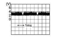
CHECK A/C SWITCH ASSEMBLY LIN SIGNAL
-
-
Connect A/C switch assembly connector.
-
Ignition switch ON.
-
Confirm output waveform between A/C switch assembly harness connector and ground with oscilloscope.
+
-
Output waveform
A/C switch assembly
Connector
Terminal
M59
8
Ground
-
Is the inspection result normal?
YES >>Replace A/C switch assembly. Refer to Removal and Installation.
NO >>GO TO 5.
-
-
CHECK LIN COMMUNICATION SIGNAL CIRCUIT FOR OPEN
-
-
Ignition switch OFF.
-
Disconnect A/C switch assembly connector and A/C amp. connector.
-
Check continuity between A/C switch assembly harness connector and A/C amp. harness connector.
A/C switch assembly
A/C amp.
Continuity
Connector
Terminal
Connector
Terminal
M59
8
M82
68
Yes
-
Is the inspection result normal?
YES >>GO TO 6.
NO >>Repair harness or connector.
-
-
CHECK LIN COMMUNICATION SIGNAL CIRCUIT FOR SHORT
-
-
Check continuity between A/C switch assembly harness connector and ground.
A/C switch assembly
—
Continuity
Connector
Terminal
M59
8
Ground
No
-
Check voltage between A/C switch assembly harness connector and ground.
+
-
Voltage
(Approx.)
A/C switch assembly
Connector
Terminal
M59
8
Ground
0 V
-
Is the inspection result normal?
YES >>Replace A/C amp. Refer to Removal and Installation.
NO >>Repair harness or connector.
-
Other materials:
Intelligent Key Battery. Removal and Installation
Removal and Installation
Removal and
Installation
Release the lock knob at the back of the Intelligent
Key and remove the mechanical key.
Insert remover tool (A) wrapped with a cloth into
the slit of the corner and twist it to separate the upper par ...
Sonar System. Basic Inspection
Diagnosis and Repair Work Flow. Work Flow
Work Flow
Work Flow
OVERALL SEQUENCE
Reference 1: Refer to CONSULT Function.
Reference 2: Refer to DTC Index.
Reference 3: Refer to Symptom Table.
DETAILED FLOW
INTERVIEW AND SYMPTO ...
P2809-00 Pressure Control Solenoid G
Dtc Description
DTC Description
DTC DETECTION LOGIC
DTC
CONSULT screen terms
(Trouble diagnosis
content)
DTC detection
...