Nissan Sentra B18 (2020-2025) Service Manual: Diagnosis System (tcm)
Diagnosis Description
1 Trip Detection Diagnosis and 2 Trip Detection Diagnosis
1 Trip Detection Diagnosis and 2 Trip Detection Diagnosis
Note:
ŌĆ£Start the engine and turn OFF the ignition switch after warm-up.ŌĆØ This is defined as 1 trip.
1 TRIP DETECTION DIAGNOSIS
When initial malfunction is detected, TCM memorizes DTC. In these diagnoses, some illuminate MIL and some do not. Refer to DTC Index.
2 TRIP DETECTION DIAGNOSIS
When initial malfunction is detected, TCM memorizes DTC of the 1st trip. MIL does not light at this stage. <1 trip>
If the same malfunction is detected again in next driving, TCM memorizes DTC. When DTC is memorized, MIL lights. <2 trip>
ŌĆ£TripŌĆØ of the ŌĆ£2 trip detection diagnosisŌĆØ indicates the driving mode that executes self-diagnosis during driving.
├Ś: Check possibleŌĆāŌĆö: Check not possible|
Item |
DTC at the 1st trip |
DTC |
MIL |
|||
|---|---|---|---|---|---|---|
|
Display at the 1st trip |
Display at the 2nd trip |
Display at the 1st trip |
Display at the 2nd trip |
Illumination at the 1st trip |
Illumination at the 2nd trip |
|
|
1 trip detection diagnosis (Refer to DTC Index) |
ŌĆö |
ŌĆö |
├Ś |
ŌĆö |
├Ś |
ŌĆö |
|
2 trip detection diagnosis (Refer to DTC Index) |
├Ś |
ŌĆö |
ŌĆö |
├Ś |
ŌĆö |
├Ś |
Dtc and Dtc of 1st Trip
DTC and DTC of 1st Trip
2 TRIP DETECTION DIAGNOSIS THAT ILLUMINATES MIL
-
The DTC number of the 1st trip is the same as the DTC number.
-
When a malfunction is detected at the 1st trip, TCM memorizes DTC of the 1st trip. MIL does not light at this stage. If the same malfunction is not detected at the 2nd trip (conforming to necessary driving conditions), DTC at the 1st trip is erased from TCM. If the same malfunction is detected at the 2nd trip, TCM memorizes DTC and MIL lights at the same time.
-
The DTC of the 1st trip is specified in Service $07 of SAE J1979/ISO 15031-5. Since detection of DTC at the 1st trip does not illuminate MIL, warning for a problem is not given to a driver.
-
For procedure to delete DTC and 1st trip DTC from TCM, refer to CONSULT Function.
-
If DTC of the 1st trip is detected, it is necessary to check the cause according to the ŌĆ£Diagnosis flowŌĆØ. Refer to Work Flow.
Malfunction Indicator Lamp (mil)
Malfunction Indicator Lamp (MIL)
-
TCM not only detects DTC, but also sends the MIL signal to ECM through CAN communication. ECM sends the MIL signal to the combination meter through CAN communication according to the signal, and illuminates MIL.
-
For malfunction indicator lamp (MIL) description, refer to Diagnosis Description.
Permanent Diagnostic Trouble Code
Permanent Diagnostic Trouble Code
Permanent DTC is defined in SAE J1979/ISO 15031-5 Service $0A.
TCM stores a DTC issuing a command of turning on MIL as a permanent DTC and keeps storing the DTC as a permanent DTC until TCM judges that there is no presence of malfunction.
Permanent DTCs cannot be erased by using the erase function of CONSULT or Generic Scan Tool (GST) and by disconnecting the battery to shut off power to TCM. This prevents a Nissan Sentra vehicle from passing the in-use inspection without repairing a malfunctioning part.
When not passing the in-use inspection due to more than one permanent DTC, permanent DTCs should be erased, referring to this manual.
Note:
-
Permanent DTCs never apply for regions that permanent DTCs are not regulated by law.
Counter System
Counter System
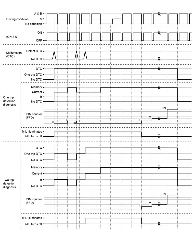
RELATION BETWEEN DTC AT 1ST TRIP/DTC/MIL AND DRIVING CONDITIONS (FOR 2 TRIP DETECTION DIAGNOSIS THAT ILLUMINATES MIL)
-
When initial malfunction is detected, TCM memorizes DTC of the 1st trip. MIL does not light at this stage.
-
If the same malfunction is detected at the 2nd trip, TCM memorizes DTC and MIL lights at the same time.
-
Then, MIL goes off after driving the Nissan Sentra vehicle for 3 trips under ŌĆ£Driving condition BŌĆØ without malfunction.
-
DTC is displayed until 40 trips of ŌĆ£Driving condition AŌĆØ are satisfied with no malfunction on "Driving condition A" after MIL lighting off. DTC is erased when 40 trips are satisfied.
-
When the self-diagnosis result is acceptable at the 2nd trip (conforming to driving condition B), DTC of the 1st trip is erased.
COUNTER SYSTEM LIST
|
Item |
Driving condition |
Trip |
|---|---|---|
|
MIL (OFF) |
B |
3 |
|
DTC (clear) |
A |
40 |
|
DTC at 1st trip (clear) |
B |
1 |
DRIVING CONDITION
Driving condition A
Driving condition A is the driving condition that provides warm-up.
In specific, count-up is performed when all of the following conditions are satisfied.
-
Engine speed is 400 rpm or more.
-
After start of the engine, the water temperature increased by 20┬░C (36┬░F) or more.
-
Water temperature was 70┬░C (158┬░F) or more.
-
The ignition switch was changed from ON to OFF.
-
If the same malfunction is detected regardless of the driving condition, reset the A counter.
-
When the above is satisfied without detecting the same malfunction after turning off MIL, count up the A counter.
-
When MIL goes off due to the malfunction and the A counter reaches 40, the DTC is erased.
Driving condition B
Driving condition B is different by each DTC.
Driving condition of count up for each DTC is as follows;
-
Diagnosis condition* and diagnosis delay time* for each DTC are satisfied.
-
While the above "1" condition is satisfied, threshold* for each DTC is not satisfied.
*: For details of these, refer to DTC/CIRCUIT DIAGNOSIS >> DTC (Pxxxx or Uxxxx) >> DTC Description >> DTC DETECTION LOGIC.
Note:
-
If the same malfunction is detected regardless of the driving condition, reset the B counter.
-
When the above is satisfied without detecting the same malfunction, count up the B counter.
-
When the B counter reaches 3 without malfunction, MIL goes off.
-
When the B counter is counted once without detecting the same malfunction after TCM memorizes DTC of the 1st trip, DTC of the 1st trip is erased.
TIME CHART
Consult Function
CONSULT Function
CAUTION:
After disconnecting the CONSULT vehicle interface (VI) from the data link connector, the ignition must be cycled OFF ŌåÆ ON (for at least 5 seconds) ŌåÆ OFF. If this step is not performed, the BCM may not go to ŌĆ£sleep modeŌĆØ, potentially causing a discharged battery and a no-start condition.
APPLICABLE ITEM
|
Diagnosis mode |
CGW Status |
Description |
||
|---|---|---|---|---|
|
Restricted Mode |
Diag Test Mode |
Open Mode |
||
|
Self Diagnostic Result |
Display |
Display |
Display |
Display non-network DTC which TCM memorizes |
|
CGW Information*1 |
Display*1 |
Display*1 |
Display*1 |
|
|
Data Monitor |
Display |
Display |
Display |
Displays TCM input/output data in real time |
|
Work Support*1 |
Non-display*1 |
Non-display*1 |
Display*1 |
This mode enables a technician to adjust some devices faster and more accurately |
|
ECU Identification |
Display |
Display |
Display |
Displays TCM part number |
|
CALIB DATA |
Display |
Display |
Display |
The calibration data status of TCM can be checked |
|
Network-DTC*2 |
Display |
Display |
Display |
Display network DTC which TCM memorizes when performing "Diagnosis (All System)" |
|
CAN Diag Support Monitor*2 |
Display |
Display |
Display |
Note:
The mode is indicated, but not monitored |
|
MAC Diagnosis |
Display |
Display |
Display |
Display MAC diagnosis result divided into the following two inspection priorities.
|
*1: In some Nissan Sentra vehicles, it is not malfunctioning in case of no display of "CGW Information". In this case, it is not necessary to switch the CGW status. In Nissan Sentra vehicles where "CGW information" is not displayed, "Work Support" is always displayed.
*2: Displays when performing "Diagnosis (All System)".
CGW INFORMATION
Display the diagnosis mode which a user can perform in Diag Test mode/Open Mode by switching the CGW status from Restricted mode to Diag Test Mode/Open Mode.
For the method of switching CAN Gateway status, Refer to CONSULT Function.
Note:
In some Nissan Sentra vehicles, it is not malfunctioning in case of no display of "CGW Information". In this case, it is not necessary to switch the CGW status.
SELF DIAGNOSTIC RESULTS
Refer to DTC Index.
DTC at 1st trip and method to read DTC
-
DTC (P0705, P0712, P0715, etc.) is specified by SAE J2012/ISO 15031-6.
-
DTC and DTC at 1st trip are displayed on ŌĆ£Self Diagnostic resultsŌĆØ of CONSULT.
When DTC is currently detected, ŌĆ£CRNTŌĆØ is displayed. If ŌĆ£PASTŌĆØ is displayed, it shows a malfunction occurred in the past. The trip number of drive without malfunction of concerned DTC can be confirmed with ŌĆ£IGN counterŌĆØ inside ŌĆ£FFDŌĆØ.
-
When the DTC at the 1st trip is detected, ŌĆ£1tŌĆØ is displayed.
DTC deletion method
Note:
If the ignition switch is left ON after repair, turn OFF the ignition switch and wait for 10 seconds or more. Then, turn the ignition ON again. (Engine stop)
-
Touch ŌĆ£TRANSMISSIONŌĆØ of CONSULT.
-
Touch ŌĆ£Self Diagnostic ResultŌĆØ.
-
Touch ŌĆ£EraseŌĆØ. (DTC memorized in TCM is erased.)
IGN counter
The ignition counter is displayed in ŌĆ£FFDŌĆØ and the number of times of satisfied ŌĆ£Driving condition AŌĆØ is displayed after normal recovery of DTC. Refer to Counter System.
-
If malfunction (DTC) is currently detected, ŌĆ£0ŌĆØ is displayed.
-
After normal recovery, every time ŌĆ£Driving condition AŌĆØ is satisfied, the display value increases from 1 ŌåÆ 2 ŌåÆ 3...38 ŌåÆ 39.
-
When MIL turns OFF due to the malfunction and the counter reaches 40, the DTC is erased.
Note:
The counter display of ŌĆ£40ŌĆØ cannot be checked.
Freeze Frame Data (FFD)
The following Nissan Sentra vehicle status is recorded when DTC is detected and is displayed on CONSULT.
|
Monitored item |
Displayed contents |
|---|---|
|
ODO/TRIP METER |
Displays the mileage at the time the malfunction is detected. |
|
DTC count (Count) |
Displays the number of times DTC is detected. |
DATA MONITOR
Note:
The following table includes information (items) inapplicable to this Nissan Sentra vehicle. For information (items) applicable to this vehicle, refer to CONSULT display items.
|
Monitored item |
(Unit) |
Remarks |
|---|---|---|
|
MANU MODE SIGNAL |
|
|
|
Ds mode signal |
|
|
|
M GEAR POS |
|
|
|
2WD/4WD identification |
Displays the axle type of the Nissan Sentra vehicle. |
|
|
Range switch 1 status |
Displays the status of transmission range switch 1 circuit. Normal: Circuit normal Open: Circuit open Low: Intermediate potential (Low) High: Intermediate potential (High) |
|
|
Range switch 2 status |
Displays the status of transmission range switch 2 circuit. Normal: Circuit normal Open: Circuit open Low: Intermediate potential (Low) High: Intermediate potential (High) |
|
|
Range switch 3 status |
Displays the status of transmission range switch 3 circuit. Normal: Circuit normal Open: Circuit open Low: Intermediate potential (Low) High: Intermediate potential (High) |
|
|
Range switch 4 status |
Displays the status of transmission range switch 4 circuit. Normal: Circuit normal Open: Circuit open Low: Intermediate potential (Low) High: Intermediate potential (High) |
|
|
PRI SPEED SEN |
Displays the status of the primary speed sensor circuit. Normal: Circuit normal Open: Circuit open Low: Intermediate potential (Low) High: Intermediate potential (High) |
|
|
SEC REV SENSOR |
Displays the status of the secondary speed sensor circuit. Normal: Circuit normal Open: Circuit open Low: Intermediate potential (Low) High: Intermediate potential (High) |
|
|
INPUT SPEED SENSOR |
Displays the status of the input speed sensor circuit. Normal: Circuit normal Open: Circuit open Low: Intermediate potential (Low) High: Intermediate potential (High) |
|
|
T/M warning indicator DTC |
Displays the first DTC when CVT system warning is displayed. |
|
|
Electric oil pump target speed |
Displays the electric oil pump target speed. |
|
|
Electric oil pump speed |
Displays the electric oil pump actual speed. |
|
|
IDLE SW |
Displays the reception status of the closed throttle position signal received through CAN communication. |
|
|
STRDWNSW |
|
|
|
STRUPSW |
|
|
|
CVT LAMP |
|
|
|
VDC ON |
Displays the reception status of the VDC operation signal received through CAN communication. |
|
|
TCS ON |
Displays the reception status of the TCS operation signal received through CAN communication. |
|
|
ABS FAIL SIGNAL |
Displays the reception status of the ABS malfunction signal received through CAN communication. |
|
|
ABS ON |
Displays the reception status of the ABS operation signal received through CAN communication. |
|
|
G SEN CALIBRATION |
Displays the status of ŌĆ£G SENSOR CALIBRATIONŌĆØ in ŌĆ£Work SupportŌĆØ. |
|
|
N IDLE STATUS |
|
|
|
Back-up lamp relay monitor |
Display back-up lamp relay status. |
|
|
Back-up lamp relay instructions |
Display instruction status from TCM to back-up lamp relay. |
|
|
RANGE SW 1 |
Displays the ON/OFF of transmission range switch 1. |
|
|
RANGE SW 2 |
Displays the ON/OFF of transmission range switch 2. |
|
|
RANGE SW 3 |
Displays the ON/OFF of transmission range switch 3. |
|
|
RANGE SW 4 |
Displays the ON/OFF of transmission range switch 4. |
|
|
Electric oil pump temp sensor |
Displays the temperature sensor status of electric oil pump. |
|
|
Electric oil pump over current |
Displays the over current status of electric oil pump. |
|
|
Electric oil pump angle sensor |
Displays the angle sensor status of electric oil pump. |
|
|
Electric oil pump low voltage |
Displays the low voltage status of electric oil pump. |
|
|
Electric oil pump over temp |
Displays the over temperature status of electric oil pump. |
|
|
Electric oil pump signal |
Displays the communication signal status of electric oil pump. |
|
|
Electric oil pump over voltage |
Displays the over voltage status of electric oil pump. |
|
|
ENGBRKLVL |
Displays the setting of ŌĆ£ENGINE BRAKE ADJŌĆØ in ŌĆ£Work SupportŌĆØ. |
|
|
CVTF DETERIORATION DATE |
This monitor item do not use. |
|
|
GAIN LU |
This monitor item do not use. |
|
|
OFFSET LU |
This monitor item do not use. |
|
|
MAP NO LU |
This monitor item do not use. |
|
|
OFFSET2 LU |
This monitor item do not use. |
|
|
GAIN PL |
This monitor item do not use. |
|
|
OFFSET PL |
This monitor item do not use. |
|
|
MAP NO PL |
This monitor item do not use. |
|
|
OFFSET2 PL |
This monitor item do not use. |
|
|
GAIN PRI |
This monitor item do not use. |
|
|
OFFSET PRI |
This monitor item do not use. |
|
|
MAP NO PRI |
This monitor item do not use. |
|
|
OFFSET2 PRI |
This monitor item do not use. |
|
|
Secondary calibration gain |
This monitor item do not use. |
|
|
Secondary calibration offset |
This monitor item do not use. |
|
|
Secondary calibration map No. |
This monitor item do not use. |
|
|
Secondary calibration offset 2 |
This monitor item do not use. |
|
|
GAIN L/B |
This monitor item do not use. |
|
|
OFFSET L/B |
This monitor item do not use. |
|
|
MAP NO L/B |
This monitor item do not use. |
|
|
OFFSET2 L/B |
This monitor item do not use. |
|
|
INIT OFFSET LB C |
This monitor item do not use. |
|
|
INIT OFFSET LB D |
This monitor item do not use. |
|
|
INIT OFFSET LB E |
This monitor item do not use. |
|
|
INIT OFFSET LB F |
This monitor item do not use. |
|
|
INIT OFFSET SLCT E |
This monitor item do not use. |
|
|
INIT OFFSET SLCT F |
This monitor item do not use. |
|
|
INIT OFFSET SLCT G |
This monitor item do not use. |
|
|
INIT OFFSET H/R A |
This monitor item do not use. |
|
|
INIT OFFSET H/R B |
This monitor item do not use. |
|
|
INIT OFFSET H/R C |
This monitor item do not use. |
|
|
INIT OFFSET H/R D |
This monitor item do not use. |
|
|
INIT OFFSET H/R E |
This monitor item do not use. |
|
|
INIT OFFSET H/R F |
This monitor item do not use. |
|
|
INIT OFFSET LB A |
This monitor item do not use. |
|
|
INIT OFFSET LB B |
This monitor item do not use. |
|
|
Lock-up extraolated value 1.1 |
This monitor item do not use. |
|
|
Lock-up extraolated value 1.2 |
This monitor item do not use. |
|
|
Lock-up extraolated version |
This monitor item do not use. |
|
|
Control valve Identification ID |
This monitor item do not use. |
|
|
Calibration version |
This monitor item do not use. |
|
|
ID 1 |
This monitor item do not use. |
|
|
ID 2 |
This monitor item do not use. |
|
|
Control valve part number 1 |
This monitor item do not use. |
|
|
Control valve part number 2 |
This monitor item do not use. |
|
|
Control valve part number 3 |
This monitor item do not use. |
|
|
Control valve part number 4 |
This monitor item do not use. |
|
|
Control valve part number 5 |
This monitor item do not use. |
|
|
Control valve part number 6 |
This monitor item do not use. |
|
|
Control valve part number 7 |
This monitor item do not use. |
|
|
Control valve part number 8 |
This monitor item do not use. |
|
|
Control valve production year |
This monitor item do not use. |
|
|
C/V production line code |
This monitor item do not use. |
|
|
C/V production month |
This monitor item do not use. |
|
|
Control valve serialnumber 1 |
This monitor item do not use. |
|
|
Control valve serialnumber 2 |
This monitor item do not use. |
|
|
Control valve serialnumber 3 |
This monitor item do not use. |
|
|
Control valve serialnumber 4 |
This monitor item do not use. |
|
|
Control valve serialnumber 5 |
This monitor item do not use. |
|
|
Control valve serialnumber 6 |
This monitor item do not use. |
|
|
C/V model information |
This monitor item do not use. |
|
|
SLCT INITIALIZE LEARN |
This monitor item do not use. |
|
|
LU INITIALIZE LEARN |
This monitor item do not use. |
|
|
SLCT INITIALIZE TEMP |
This monitor item do not use. |
|
|
LU INITIALIZE TEMP |
This monitor item do not use. |
|
|
SLCT INITIALIZE ND PRS |
This monitor item do not use. |
|
|
SLCT INITIALIZE ND TIME |
This monitor item do not use. |
|
|
SLCT INITIALIZE NR PRS |
This monitor item do not use. |
|
|
SLCT INITIALIZE NR TIME |
This monitor item do not use. |
|
|
LU INITIALIZE LEARN 1 |
This monitor item do not use. |
|
|
LU INITIALIZE LEARN 2 |
This monitor item do not use. |
|
|
Clearance No. |
This monitor item do not use. |
|
|
Unit manufacturing date 1 |
This monitor item do not use. |
|
|
Unit manufacturing date 2 |
This monitor item do not use. |
|
|
Unit manufacturing date 3 |
This monitor item do not use. |
|
|
Unit manufacturing date 4 |
This monitor item do not use. |
|
|
Unit manufacturing date 5 |
This monitor item do not use. |
|
|
Unit manufacturing date 6 |
This monitor item do not use. |
|
|
Unit part number 1 |
This monitor item do not use. |
|
|
Unit part number 2 |
This monitor item do not use. |
|
|
Unit part number 3 |
This monitor item do not use. |
|
|
Unit part number 4 |
This monitor item do not use. |
|
|
Unit part number 5 |
This monitor item do not use. |
|
|
Unit part number 6 |
This monitor item do not use. |
|
|
Unit part number 7 |
This monitor item do not use. |
|
|
Unit part number 8 |
This monitor item do not use. |
|
|
Unit production year |
This monitor item do not use. |
|
|
Unit production line code |
This monitor item do not use. |
|
|
Unit production month |
This monitor item do not use. |
|
|
Unit serial number 1 |
This monitor item do not use. |
|
|
Unit serial number 2 |
This monitor item do not use. |
|
|
Unit serial number 3 |
This monitor item do not use. |
|
|
Unit serial number 4 |
This monitor item do not use. |
|
|
Unit serial number 5 |
This monitor item do not use. |
|
|
Unit serial number 6 |
This monitor item do not use. |
|
|
Unit model Information |
This monitor item do not use. |
|
|
VSP SENSOR |
(km/h or mph) |
Displays the Nissan Sentra vehicle speed calculated from the CVT output shaft speed. |
|
SLIP REV |
(rpm) |
Displays the speed difference between the input shaft speed of CVT and the engine speed. |
|
Line pressure |
(MPa) |
Displays the line pressure calculated from the signal voltage of the line pressure sensor. |
|
Line pressure sensor |
(V) |
Displays the signal voltage of the line pressure sensor. |
|
TRQ RTO |
Display the torque ratio of torque converter. |
|
|
G sensor (TCM) |
(V) |
|
|
BRAKESW |
Displays the reception status of the stop lamp switch signal received through CAN communication. |
|
|
SHIFT IND SIGNAL |
Displays the shift position signal transmitted via CAN communication. |
|
|
RANGE |
Displays the gear position recognized by TCM. |
|
|
ESTM VSP SIG |
(km/h or mph) |
Displays the Nissan Sentra vehicle speed signal (ABS) received through CAN communication. |
|
VIGN SEN |
(V) |
Displays the battery voltage applied to TCM. |
|
PVIGN VOLT |
(V) |
Displays the backup voltage of TCM. |
|
Nissan Sentra Vehicle SPEED |
(km/h or mph) |
Displays the Nissan Sentra vehicle speed recognized by TCM. |
|
INPUT REV |
(rpm) |
Displays the input shaft speed of CVT recognized by TCM. |
|
PRI SPEED |
(rpm) |
Displays the primary pulley speed recognized by TCM. |
|
SEC SPEED |
(rpm) |
Displays the secondary pulley speed recognized by TCM. |
|
ENG SPEED |
(rpm) |
Displays the engine speed recognized by TCM. |
|
PULLEY GEAR RATIO |
Displays the pulley gear ratio calculated from primary pulley speed/secondary pulley speed. |
|
|
G SPEED |
(G) |
Displays the acceleration and deceleration speed of the Nissan Sentra vehicle calculated from vehicle speed change. |
|
ACCEL POSI SEN 1 |
(deg) |
Displays the estimated throttle position received through CAN communication. |
|
VENG TRQ |
(Nm) |
Display the engine torque recognized by TCM. |
|
PRI TRQ |
(Nm) |
Display the input shaft torque of CVT. |
|
SEC PRESSURE |
(MPa) |
Displays the secondary pressure calculated from the signal voltage of the secondary pressure sensor. |
|
PRI PRESSURE |
(MPa) |
Displays the primary pressure calculated from the signal voltage of the primary pressure sensor. |
|
FLUID TEMP |
(┬░C or ┬░F) |
Displays the CVT fluid temperature calculated from the signal voltage of the CVT fluid temperature sensor. |
|
DSR REV |
(rpm) |
Displays the target primary pulley speed calculated from processing of gear shift control. |
|
TRGT GEAR RATIO |
Displays the target gear ratio of the pulley from processing of gear shift control. |
|
|
LU PRS |
(MPa) |
Displays the target oil pressure of the torque converter clutch solenoid calculated from oil pressure processing of gear shift control. |
|
LINE PRS |
(MPa) |
Displays the target oil pressure of the line pressure solenoid valve calculated from oil pressure processing of gear shift control. |
|
TRGT PRI PRESSURE |
(MPa) |
Displays the target oil pressure of the primary pressure solenoid valve calculated from oil pressure processing of gear shift control. |
|
Target select pressure |
(MPa) |
Displays the target oil pressure of the select solenoid valve calculated from oil pressure processing of gear shift control. |
|
TARGET SEC PRESSUR |
(MPa) |
Displays the target oil pressure of the secondary pressure solenoid valve calculated from oil pressure processing of gear shift control. |
|
ISOLT1 |
(mA) |
Displays the command current from TCM to the torque converter clutch solenoid. |
|
ISOLT2 |
(mA) |
Displays the command current from TCM to the line pressure solenoid valve. |
|
PRI SOLENOID |
(mA) |
Displays the command current from TCM to the primary pressure solenoid valve. |
|
SEC SOLENOID CURRENT |
(mA) |
Displays the command current from TCM to the secondary pressure solenoid valve. |
|
SELECT SOLENOID CURRENT |
(mA) |
Displays the command current from TCM to the select solenoid valve. |
|
SOLMON1 |
(mA) |
Monitors the command current from TCM to the torque converter clutch solenoid and displays the monitored value. |
|
SOLMON2 |
(mA) |
Monitors the command current from TCM to the line pressure solenoid valve and displays the monitored value. |
|
PRI SOL MON |
(mA) |
Monitors the command current from TCM to the primary pressure solenoid valve and displays the monitored value. |
|
SEC SOL MON CURRENT |
(mA) |
Monitors the command current from TCM to the secondary pressure solenoid valve and displays the monitored value. |
|
SELECT SOL MON CURRENT |
(mA) |
Monitors the command current from TCM to the select solenoid valve and displays the monitored value. |
|
G SEN SLOPE |
(%) |
Displays the gradient angle calculated from the G sensor signal voltage. |
|
CVT-B |
|
|
|
CVT-A |
|
|
|
Slip revolution absolute value |
(rpm) |
This monitor item do not use. |
|
Target transmission speed |
(sec) |
This monitor item do not use. |
|
Input speed sensor |
(rpm) |
Displays the input speed calculated from the pulse signal of the input speed sensor. |
|
PRI SPEED SEN |
(rpm) |
Displays the primary pulley speed calculated from the pulse signal of the primary speed sensor. |
|
SEC REV SENSOR |
(rpm) |
Displays the secondary pulley speed calculated from the pulse signal of the secondary speed sensor. |
|
ENG SPEED SIG |
(rpm) |
Displays the engine speed received through CAN communication. |
|
SEC PRESSURE SEN |
(V) |
Displays the signal voltage of the secondary pressure sensor. |
|
PRI PRESSURE SEN |
(V) |
Displays the signal voltage of the primary pressure sensor. |
|
ATF TEMP SEN |
(V) |
Displays the signal voltage of the CVT fluid temperature sensor. |
|
G SENSOR |
(G) |
Displays the signal voltage of the G sensor. |
WORK SUPPORT
|
Item name |
Description |
|---|---|
| ENGINE BRAKE ADJ. | Although there is no malfunction on the transaxle and the CVT system, if a customer make a complaint like ŌĆ£I do not feel comfortable with automatic operation of the engine brake on downhillŌĆØ, the engine brake may be cancelled with ŌĆ£engine brake adjustmentŌĆØ. |
| CONFORM CVTF DETERIORTN | Checks the degradation level of the CVT fluid under severe conditions. |
| READ IP CHARA - REPLACEMENT TCM | Reads IP characteristics when TCM is replaced. |
| WRITE IP CHARA - REPLACEMENT TCM | Writes IP characteristics when TCM is replaced. |
| WRITE IP CHARA - REPLACEMENT AT/CVT | Writes IP characteristics when transaxle assembly/control valve is replaced. |
| WRITE IP CHARA - INPUT SERIAL NUMBER | Writes IP characteristics that matches the serial number of transaxle assembly or control valve. |
| ERASE LEARNING VALUE |
|
| FORWARD CLUTCH POINT LEARNING | Allows learning of the forward clutch engagement point. |
| TORQUE CONVERTER CLUTCH POINT LERNING | Allows learning of the torque converter clutch meet point. |
| G SENSOR CALIBRATION | Compensates the G sensor. |
Engine brake adjustment
|
ENGINE BRAKE LEVEL |
|
|
ON |
: Turn ON the engine brake control. |
|
OFF |
: Turn OFF the engine brake control. |
Check the degradation level of the CVT fluid.
|
CVTF degradation level data |
|
|
210,000 or more |
: Replacement of the CVT fluid is required. |
|
Less than 210,000 |
: Replacement of the CVT fluid is not required. |
Other materials:
B2223-16 Combination Meter
Dtc Description
DTC Description
DTC DETECTION LOGIC
DTC No.
CONSULT screen terms
(Trouble diagnosis
content)
DTC detected condition
...
P27a6-00 Electric Oil Pump
Dtc Description
DTC Description
DTC DETECTION LOGIC
DTC
CONSULT screen terms
(Trouble diagnosis
content)
DTC detection
conditi ...
Operation
Automatic Speed Control Device (ascd)
Switch Name and Function
Switch Name and Function
SWITCHES AND INDICATORS
On the combination
meter
...