Nissan Sentra B18 (2020-2025) Service Manual: Ecu Diagnosis Information. Ipdm E/r (intelligent Power Distribution Module Engine Room)
Ipdm E/r (intelligent Power Distribution Module Engine Room)
Values on the Diagnosis Tool
Values on the Diagnosis Tool
Note:
The following table includes information (items) inapplicable to this Nissan Sentra vehicle. For information (items) applicable to this vehicle, refer to CONSULT display items.
|
Monitor |
Condition |
Value/Status |
|
|---|---|---|---|
|
Hood switch Note:
This item is monitored only on the Nissan Sentra vehicle with remote engine start system. |
Close the hood |
Open |
|
|
Open the hood |
Close |
||
|
IGN RELAY |
Ignition switch OFF |
Open |
|
|
Ignition switch ON |
Close |
||
|
REVERSE SIGNAL |
Ignition switch ON |
|
Open |
|
Close |
||
|
NEUTRAL SW Note:
This item is monitored only on the Nissan Sentra vehicle with M/T. |
Ignition switch ON |
Shift selector in any position other than neutral |
Open |
|
Shift selector in neutral position |
Close |
||
|
Stop/start permit Note:
This item is monitored only on the Nissan Sentra vehicle with idle start/stop system. |
Idle start/stop system operation condition |
Not satisfied |
Open |
|
Satisfied |
Close |
||
|
Headlamp warning (RH) Note:
This item is monitored only on the Nissan Sentra vehicle with LED headlamp. |
Lighting switch OFF |
Open |
|
|
Lighting switch 2ND |
Close |
||
|
Headlamp warning (LH) Note:
This item is monitored only on the Nissan Sentra vehicle with LED headlamp. |
Lighting switch OFF |
Open |
|
|
Lighting switch 2ND |
Close |
||
|
Rear height sensor |
Ignition switch ON |
Headlamp aiming switch in 0 position |
4 V |
|
Headlamp aiming switch in 1 position |
Voltage decreases from the 0 position status of the headlamp aiming switch |
||
|
Headlamp aiming switch in 2 position |
Voltage decreases from the 1 position status of the headlamp aiming switch |
||
|
Headlamp aiming switch in 3 position |
Voltage decreases from the 2 position status of the headlamp aiming switch |
||
|
Cooling fan relay-2 |
Engine running |
Cooling fan stop |
OFF |
|
ON |
||
|
Horn relay |
Note:
This item is indicated, but not monitored. |
OFF |
|
|
Compressor |
Engine running |
A/C switch OFF |
OFF |
|
A/C switch ON [A/C compressor (magnetic clutch) is operating] |
ON |
||
|
Front wiper HI/LO relay |
Ignition switch ON |
Except front wiper HI operated |
OFF |
|
Front wiper HI operated |
ON |
||
|
Front wiper relay |
Ignition switch ON |
Front wiper stop |
OFF |
|
Front wiper is operating |
ON |
||
|
Ignition relay off status |
Ignition switch ON |
OFF |
|
|
Ignition switch OFF |
ON |
||
|
Ignition relay on status |
Ignition switch OFF |
OFF |
|
|
Ignition switch ON |
ON |
||
|
Starter relay |
Note:
This item is indicated, but not monitored. |
OFF |
|
|
Compressor ECV duty |
Engine running |
A/C switch OFF |
0% |
|
A/C switch ON [A/C compressor (ECV) is operating) |
0 – 100% |
||
|
Cooling fan relay-3 |
Engine running |
|
0% |
|
Cooling fan HI operated |
100% |
||
|
Front fog lamp (LH) Note:
This item is monitored only on the Nissan Sentra vehicle with front fog lamp. |
Lighting switch 1ST |
Front fog lamp switch OFF |
0% |
|
Front fog lamp switch ON |
100% |
||
|
Front fog lamp (RH) Note:
This item is monitored only on the Nissan Sentra vehicle with front fog lamp. |
Lighting switch 1ST |
Front fog lamp switch OFF |
0% |
|
Front fog lamp switch ON |
100% |
||
|
Levelizer output |
Lighting switch 2ND |
Headlamp aiming switch in 0 position |
78.800% |
|
Headlamp aiming switch in 1 position |
Value decreases from the 0 position status of the headlamp aiming |
||
|
Headlamp aiming switch in 2 position |
Value decreases from the 1 position status of the headlamp aiming |
||
|
Headlamp aiming switch in 3 position |
Value decreases from the 2 position status of the headlamp aiming |
||
|
Tail lamp (LH) |
Lighting switch OFF |
0.0% |
|
|
Lighting switch 1ST |
100.0% |
||
|
Tail lamp (RH) |
Lighting switch OFF |
0% |
|
|
Lighting switch 1ST |
100% |
||
|
Daytime running light (LH) Note:
This item is monitored only on the Nissan Sentra vehicle with daytime running light system. |
Engine stop |
Lighting switch OFF |
0.0% |
|
Engine running |
Lighting switch OFF |
100.0% |
|
|
Lighting switch 1ST |
24.0% |
||
|
Daytime running light (RH) Note:
This item is monitored only on the Nissan Sentra vehicle with daytime running light system. |
Engine stop |
Lighting switch OFF |
0.0% |
|
Engine running |
Lighting switch OFF |
100.0% |
|
|
Lighting switch 1ST |
24.0% |
||
|
Headlamp HI (LH) |
Lighting switch 2ND |
Lighting switch LO |
0% |
|
Lighting switch HI or PASS |
100% |
||
|
Headlamp HI (RH) |
Lighting switch 2ND |
Lighting switch LO |
0% |
|
Lighting switch HI or PASS |
100% |
||
|
Headlamp LO (RH) |
Lighting switch OFF |
0% |
|
|
Lighting switch 2ND |
100% |
||
|
Headlamp LO (LH) |
Lighting switch OFF |
0% |
|
|
Lighting switch 2ND |
100% |
||
|
Parking lamp (RH) |
Lighting switch OFF |
Engine stop |
0.0% |
|
Engine running |
100.0% |
||
|
Lighting switch 1ST |
|||
|
Parking lamp (LH) |
Lighting switch OFF |
Engine stop |
0.0% |
|
Engine running |
100.0% |
||
|
Lighting switch 1ST |
|||
|
COMP ECV STATUS |
ECV control output |
Normal |
OK |
|
Malfunction |
NG |
||
|
Battery current sensor value |
Note:
This item is indicated, but not monitored. |
0 A |
|
|
BATTERY VOLTAGE |
Ignition switch ON |
11 V – 14 V |
|
|
Battery warning request (IPDM) |
Battery voltage |
Except 10 V or less / 16 V or more |
No Alert |
|
10 V or less / 16 V or more |
Alert |
||
|
Transmits invalid CAN signal |
Unknown |
||
|
Stop/start status Note:
This item is monitored only on the Nissan Sentra vehicle with idle start/stop system. |
Idle start/stop system error |
Error |
|
|
Idle start/stop system operation condition |
No satisfied |
Prohibit |
|
|
Satisfied |
Permit |
||
|
FR WIPER STOP POSITION |
Ignition switch ON |
Except front wiper stop position |
ACTIVE P |
|
Front wiper stop position |
STOP P |
||
|
IGNITION POWER SUPPLY |
Note:
This item is indicated, but not monitored. |
Off |
|
|
STARTER RELAY (CAN) |
Note:
This item is indicated, but not monitored. |
NG |
|
|
HOOD SW (CAN) Note:
This item is monitored only on the Nissan Sentra vehicle with idle start/stop system. |
Open the hood |
OPEN |
|
|
Close the hood |
CLOSE |
||
|
Transmits invalid CAN signal |
NG |
||
|
Front wiper |
Ignition switch ON |
Front wiper stop |
Stop |
|
Front wiper LO operation |
Low |
||
|
Front wiper HI operation |
High |
||
|
COOLING FAN DUTY |
Engine running |
Cooling fan stop |
0% |
|
Cooling fan LO operated |
25% |
||
|
Cooling fan HI operated |
100% |
||
|
A/C RELAY STUCK |
A/C compressor (magnetic clutch) power supply output |
Normal |
OK |
|
Malfunction |
NG |
||
|
Headlamp warning request Note:
This item is monitored only on the Nissan Sentra vehicle with LED headlamp. |
Ignition switch ON and lighting switch 2ND |
Headlamp low: Normal |
No req |
|
Headlamp low: Malfunction |
Request |
||
|
0.3 second after any of the following operations with the monitor status "Request":
|
Re-req |
||
|
NEUTRAL SWITCH (CAN) Note:
This item is monitored only on the Nissan Sentra vehicle with M/T. |
Ignition switch ON |
Shift selector in any position other than neutral |
Off |
|
Shift selector in neutral position |
On |
||
|
Transmits invalid CAN signal |
NG |
||
|
A/C RELAY |
Engine running |
A/C switch OFF |
Off |
|
A/C switch ON [A/C compressor (magnetic clutch) is operating] |
On |
||
|
Alternator voltage req value |
Note:
This item is indicated, but not monitored. |
0 V |
|
|
REVERSE SIGNAL (CAN) |
Ignition switch ON |
|
Off |
|
On |
||
|
Transmits invalid CAN signal |
NG |
||
|
COMP ECV CURRENT |
Engine running |
A/C switch OFF |
0.00 A |
|
A/C switch ON [A/C compressor (magnetic clutch) is operating] |
0.00 A – 1.00 A |
||
|
STARTER MOTOR STATUS |
Note:
This item is indicated, but not monitored. |
Off |
|
|
IPDM NOT SLEEP |
Note:
This item is indicated, but not monitored. |
No ready |
|
|
Starter&starter cont relay stat |
Starter relay and starter control relay are OFF |
Off, Off |
|
|
Starter relay is ON |
On, Off |
||
|
Starter relay and starter control relay are ON |
On, On |
||
|
Transmits invalid CAN signal |
invalid |
||
|
Starter control relay status |
Engine |
Not cranking |
Off |
|
Cranking |
On |
||
|
Transmits invalid CAN signal |
Unknown |
||
|
Battery temp sensor value |
Note:
This item is indicated, but not monitored. |
0°C |
|
|
Compressor request 1 |
Engine running |
A/C switch OFF |
Off |
|
A/C switch ON [A/C compressor (magnetic clutch) is operating] |
On |
||
|
Easy fill tire alert horn req |
Note:
This item is indicated, but not monitored. |
Off |
|
|
Cranking enable-TCM |
Engine crank condition |
Not satisfied |
Prohibit |
|
Satisfied |
Permit |
||
|
— |
Stop |
||
|
Receives invalid CAN signal |
Unknown |
||
|
Cranking enable-ECM |
Engine crank condition |
Not satisfied |
Prohibit |
|
Satisfied |
Permit |
||
|
— |
Stop |
||
|
Receives invalid CAN signal |
No req |
||
|
DTRL REQ Note:
This item is monitored only on the Nissan Sentra vehicle with daytime running light system. |
Engine running |
Lighting switch 1ST |
Off |
|
Lighting switch OFF |
On |
||
|
SLEEP/WAKE UP |
Note:
This item is indicated, but not monitored. |
SLEEP |
|
|
CLUTCH INTERLOCK SW |
Note:
This item is displayed only on the Nissan Sentra vehicle with M/T, but not monitored. |
Off |
|
|
TURN SIGNAL REQ |
Turn signal switch |
OFF |
Off |
|
Left |
LH |
||
|
Right |
RH |
||
|
COOLING FAN REQ |
Engine running |
Cooling fan stop |
10% |
|
Cooling fan LO operation |
42% |
||
|
Cooling fan HI operation |
90% |
||
|
FR WIPER REQ |
Ignition switch ON |
Front wiper stopped |
RETURN |
|
Front wiper forced termination |
STOP |
||
|
Front wiper LO operation |
LOW |
||
|
Front wiper HI operation |
HIGH |
||
|
Receives invalid CAN signal |
NG |
||
|
Diagnosis mask status |
Ignition switch OFF and auto ACC OFF or engine cranking |
Status 1 |
|
|
Ignition switch OFF and auto ACC ON |
Status 2 |
||
|
Ignition switch ON and battery voltage 10 V or less |
Status 3 |
||
|
Ignition switch ON and battery voltage 10 V or more |
Status 4 |
||
|
Receives invalid CAN signal |
Unknown |
||
|
PASSING REQ |
Except lighting switch PASS |
Off |
|
|
Lighting switch PASS |
On |
||
|
HIGH BEAM REQ |
Lighting switch 2ND |
Lighting switch LO |
Off |
|
Lighting switch HI |
On |
||
|
Horn request |
Note:
This item is indicated, but not monitored. |
No req |
|
|
Low beam request |
Lighting switch OFF |
Off |
|
|
Lighting switch 2ND |
On |
||
|
Engine status |
Engine |
Stop |
Stop |
|
Running |
Running |
||
|
Cranking |
Starting |
||
|
POSITION LIGHT REQ |
Lighting switch OFF |
Off |
|
|
Lighting switch 1ST |
On |
||
|
IGNITION SW |
Ignition switch OFF |
Off |
|
|
Ignition switch ON |
On |
||
|
Ignition switch START |
START |
||
|
— |
No request |
||
|
Hazard warning lamp status |
Hazard switch OFF |
Off |
|
|
Hazard switch ON |
On |
||
|
FRONT FOG LAMP REQ Note:
This item is monitored only on the Nissan Sentra vehicle with front fog lamp. |
Lighting switch 1ST |
Front fog lamp switch OFF |
Off |
|
Front fog lamp switch ON |
On |
||
|
Motor fan type |
— |
Relay fan |
|
|
Low Beam type |
Halogen headlamp |
Halogen |
|
|
LED headlamp |
LED |
||
|
STARTER OPERATION COUNT |
Note:
This item is indicated, but not monitored. |
0 Times |
|
|
H/P F/PUMP OPERATN COUNT |
Note:
This item is indicated, but not monitored. |
0 Times |
|
|
Park lamp (LH) circ malfunctn |
Parking lamp LH circuit reaches the retry upper limit. |
0 – 1 |
|
|
Nmb park lamp (LH) circ retry |
Retry of parking lamp LH circuit is permitted. |
0 – 20 |
|
|
Nmb park lamp (LH) circ short |
Parking lamp LH circuit detects over current. |
0 – 5 |
|
|
DTRL (LH) circ malfunctn Note:
This item is monitored only on the Nissan Sentra vehicle with daytime running light system. |
Daytime running light LH circuit reaches the retry upper limit. |
0 – 1 |
|
|
NMB DTRL (LH) circ retry Note:
This item is monitored only on the Nissan Sentra vehicle with daytime running light system. |
Retry of daytime running light LH circuit is permitted. |
0 – 20 |
|
|
NMB DTRL (LH) circ short Note:
This item is monitored only on the Nissan Sentra vehicle with daytime running light system. |
Daytime running light LH circuit detects over current. |
0 – 5 |
|
|
DTRL (RH) circ malfunctn Note:
This item is monitored only on the Nissan Sentra vehicle with daytime running light system. |
Daytime running light RH circuit reaches the retry upper limit. |
0 – 1 |
|
|
Nmb DTRL (RH) circ retry Note:
This item is monitored only on the Nissan Sentra vehicle with daytime running light system. |
Retry of daytime running light RH circuit is permitted. |
0 – 20 |
|
|
Nmb DTRL (RH) circ short Note:
This item is monitored only on the Nissan Sentra vehicle with front fog lamp. |
Daytime running light RH circuit detects over current. |
0 – 5 |
|
|
Fr fog lamp (LH) circ malfunctn Note:
This item is monitored only on the Nissan Sentra vehicle with front fog lamp. |
Front fog lamp LH circuit reaches the retry upper limit. |
0 – 1 |
|
|
NMB F FOG LH CIRC RETRY Note:
This item is monitored only on the Nissan Sentra vehicle with front fog lamp. |
Retry of front fog lamp LH circuit is permitted. |
0 – 20 |
|
|
NMB F FOG LH CIRC SHORT Note:
This item is monitored only on the Nissan Sentra vehicle with front fog lamp. |
Front fog lamp LH circuit detects over current. |
0 – 5 |
|
|
F FOG RH CIRC MALFUNCTN Note:
This item is monitored only on the Nissan Sentra vehicle with front fog lamp. |
Front fog lamp RH circuit reaches the retry upper limit. |
0 – 1 |
|
|
NMB F FOG RH CIRC RETRY Note:
This item is monitored only on the Nissan Sentra vehicle with front fog lamp. |
Retry of front fog lamp RH circuit is permitted. |
0 – 20 |
|
|
NMB F FOG RH CIRC SHORT Note:
This item is monitored only on the Nissan Sentra vehicle with front fog lamp. |
Front fog lamp RH circuit detects over current. |
0 – 5 |
|
|
HL (HI) LH CIRC MALFUNCTN |
Headlamp (high) LH circuit reaches the retry upper limit. |
0 – 1 |
|
|
NMB HL (HI) LH CIRC RETRY |
Retry of headlamp (high) LH circuit is permitted. |
0 – 20 |
|
|
NMB HL (HI) LH CIRC SHORT |
Headlamp (high) LH circuit detects over current. |
0 – 5 |
|
|
HL (HI) RH CIRC MALFUNCTN |
Headlamp (high) RH circuit reaches the retry upper limit. |
0 – 1 |
|
|
Nmb HL HI (RH) circ retry |
Retry of headlamp (high) RH circuit is permitted. |
0 – 20 |
|
|
Nmb HL HI (RH) circ short |
Headlamp (high) RH circuit detects over current. |
0 – 5 |
|
|
HL LO (LH) circ malfunctn |
Headlamp (low) LH circuit reaches the retry upper limit. |
0 – 1 |
|
|
Nmb HL LO (LH) circ retry |
Retry of headlamp (low) LH circuit is permitted. |
0 – 20 |
|
|
Nmb HL LO (LH) circ short |
Headlamp (low) LH circuit detects over current. |
0 – 5 |
|
|
HL LO (RH) circ malfunctn |
Headlamp (low) RH circuit reaches the retry upper limit. |
0 – 1 |
|
|
Nmb HL LO (RH) circ retry |
Retry of headlamp (low) RH circuit is permitted. |
0 – 20 |
|
|
Nmb HL LO (RH) circ short |
Headlamp (low) RH circuit detects over current. |
0 – 5 |
|
|
T LAMP LH CIRC MALFUNCTN |
Tail lamp LH circuit reaches the retry upper limit. |
0 – 1 |
|
|
NMB T LAMP LH CIRC RETRY |
Retry of tail lamp LH circuit is permitted. |
0 – 20 |
|
|
NMB T LAMP LH CIRC SHORT |
Tail lamp LH circuit detects over current. |
0 – 5 |
|
|
T LAMP RH CIRC MALFUNCTN |
Tail lamp RH circuit reaches the retry upper limit. |
0 – 1 |
|
|
NMB T LAMP RH CIRC RETRY |
Retry of tail lamp RH circuit is permitted. |
0 – 20 |
|
|
NMB T LAMP RH CIRC SHORT |
Tail lamp RH circuit detects over current. |
0 – 5 |
|
|
Park lamp (RH) circ malfunctn |
Parking lamp RH circuit reaches the retry upper limit. |
0 – 1 |
|
|
Nmb park lamp (RH) circ retry |
Retry of parking lamp RH circuit is permitted. |
0 – 20 |
|
|
Nmb park lamp (RH) circ short |
Parking lamp RH circuit detects over current. |
0 – 5 |
|
|
BAT DISCHARGE COUNT Note:
This item is monitored only on the Nissan Sentra vehicle with idle start/stop system. |
Ignition switch ON |
Less than 65000 |
|
|
BATTERY STATUS Note:
This item is monitored only on the Nissan Sentra vehicle with idle start/stop system. |
Engine: Idling |
Battery status judgement result OK |
OK |
|
Battery status judgement result NG |
NG |
||
|
Nissan Sentra Vehicle speed |
While driving |
Equivalent to speedometer reading |
|
Reference Value
Reference Value
TERMINAL LAYOUT
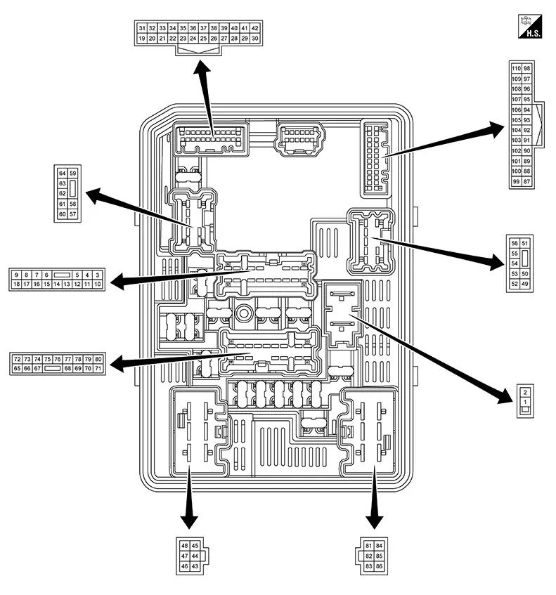
PHYSICAL VALUES
|
Terminal No. (Wire color) |
Description |
Condition |
Value (Approx.) |
|||
|---|---|---|---|---|---|---|
|
Signal name |
Input/Output |
|||||
|
+ |
- |
|||||
|
1 (G) |
Ground |
Battery power supply |
Input |
Ignition switch OFF |
Battery voltage |
|
|
2 (R) |
Ground |
Battery power supply |
Input |
Ignition switch OFF |
Battery voltage |
|
|
4 (R) |
Ground |
Tail lamp LH power supply |
Output |
Lighting switch OFF |
0 V |
|
|
Lighting switch 1ST |
Battery voltage |
|||||
|
9 (R) |
Ground |
Horn relay control |
Input |
Horn switch OFF |
Battery voltage |
|
|
Horn switch ON |
0 V |
|||||
|
11 (BG) |
Ground |
Ignition relay-1 output |
Output |
Ignition switch OFF |
0 V |
|
|
Ignition switch ON |
Battery voltage |
|||||
|
12 (B) |
Ground |
Ground |
— |
Ignition switch OFF |
0 V |
|
|
16 (G) |
Ground |
Back-up lamp power supply |
Output |
Ignition switch ON |
Shift selector in any position other than R |
0 V |
|
Shift selector in R position |
Battery voltage |
|||||
|
17 (R) |
Ground |
Tail lamp RH power supply |
Output |
Lighting switch OFF |
0 V |
|
|
Lighting switch 1ST |
Battery voltage |
|||||
|
19 (L) |
Ground |
Ignition relay-1 output |
Output |
Ignition switch OFF |
0 V |
|
|
Ignition switch ON |
Battery voltage |
|||||
|
22 (P) |
Ground |
CAN-Low |
Input/Output |
— |
— |
|
|
24 (L) |
Ground |
CAN-High |
Input/Output |
— |
— |
|
|
31 (B) |
Ground |
Ground |
— |
Ignition switch OFF |
0 V |
|
|
33 (BR) |
Ground |
Front wiper stop position signal |
Input |
Ignition switch ON |
Front wiper stop position |
0 V |
|
Other than above |
Battery voltage |
|||||
|
391 (L) |
Ground |
CAN-High |
— |
— |
— |
|
|
401 (P) |
Ground |
CAN-Low |
— |
— |
— |
|
|
45 (L) |
Ground |
Front wiper motor HI power supply |
Output |
Ignition switch ON |
Front wiper switch OFF |
0 V |
|
Front wiper switch HI |
Battery voltage |
|||||
|
46 (P) |
Ground |
Fuel pump relay output |
Output |
Ignition switch OFF |
0 V |
|
|
Ignition switch ON |
Battery voltage |
|||||
|
47 (B) |
Ground |
Ground |
— |
Ignition switch OFF |
0 V |
|
|
48 (W) |
Ground |
Front wiper motor LO power supply |
Output |
Ignition switch ON |
Front wiper switch OFF |
0 V |
|
Front wiper switch LO |
Battery voltage |
|||||
|
492 (L) |
Ground |
Daytime running light LH power supply |
Output |
Engine stop |
Lighting switch OFF |
0 V |
|
Engine running |
Battery voltage |
|||||
|
50 (BG) |
Ground |
Headlamp (low) LH power supply |
Output |
Lighting switch OFF |
0 V |
|
|
Lighting switch 2ND |
Battery voltage |
|||||
|
523 (SB) |
Ground |
Hood switch signal |
Input |
Close the hood |
0 V |
|
|
Open the hood |
Battery voltage |
|||||
|
524 (B) |
Ground |
Ground |
— |
Ignition switch OFF |
0 V |
|
|
535 (G) |
Ground |
Headlamp warning LH signal |
Input |
Lighting switch OFF |
Battery voltage |
|
|
Lighting switch 2ND |
0 V |
|||||
|
54 (Y) |
Ground |
Headlamp (high) RH power supply |
Output |
Lighting switch 2ND |
Lighting switch LO |
0 V |
|
Lighting switch HI or PASS |
Battery voltage |
|||||
|
56 (Y)6 (L)5 |
Ground |
Parking lamp LH power supply |
Output |
Lighting switch OFF |
Engine stop |
0 V |
|
Engine running |
Battery voltage |
|||||
|
Lighting switch 1ST |
||||||
|
582 (L) |
Ground |
Daytime running light RH power supply |
Output |
Engine stop |
Lighting switch OFF |
0 V |
|
Engine running |
Battery voltage |
|||||
|
59 (W) |
Ground |
Headlamp (high) LH power supply |
Output |
Lighting switch 2ND |
Lighting switch LO |
0 V |
|
Lighting switch HI or PASS |
Battery voltage |
|||||
|
605 (G) |
Ground |
Headlamp warning RH signal |
Input |
Lighting switch OFF |
Battery voltage |
|
|
Lighting switch 2ND |
0 V |
|||||
|
61 (L) |
Ground |
Parking lamp RH power supply |
Output |
Lighting switch OFF |
Engine stop |
0 V |
|
Engine running |
Battery voltage |
|||||
|
Lighting switch 1ST |
||||||
|
62 (P) |
Ground |
Headlamp (low) RH power supply |
Output |
Lighting switch OFF |
0 V |
|
|
Lighting switch 2ND |
Battery voltage |
|||||
|
65 (P) |
Ground |
A/C compressor (magnetic clutch) power supply |
Output |
Engine running |
A/C switch OFF |
0 V |
|
A/C switch ON [A/C compressor (magnetic clutch) is operating] |
Battery voltage |
|||||
|
66 (W) |
Ground |
ECM relay output |
Output |
Ignition switch OFF |
0 V |
|
|
Ignition switch ON |
Battery voltage |
|||||
|
67 (Y) |
Ground |
Throttle control motor relay control |
Input |
Ignition switch OFF |
Battery voltage |
|
|
Ignition switch ON |
0 V |
|||||
|
701 (BR) |
Ground |
Ignition relay-1 output |
Output |
Ignition switch OFF |
0 V |
|
|
Ignition switch ON |
Battery voltage |
|||||
|
71 (SB) |
Ground |
Ignition relay-1 output |
Output |
Ignition switch OFF |
0 V |
|
|
Ignition switch ON |
Battery voltage |
|||||
|
72 (R) |
Ground |
Throttle control motor relay output |
Output |
Ignition switch OFF |
0 V |
|
|
Ignition switch ON |
Battery voltage |
|||||
|
73 (G) |
Ground |
ECM relay output |
Output |
Ignition switch OFF |
0 V |
|
|
Ignition switch ON |
Battery voltage |
|||||
|
75 (V) |
Ground |
ECM relay output |
Output |
Ignition switch OFF |
0 V |
|
|
Ignition switch ON |
Battery voltage |
|||||
|
76 (GR) |
Ground |
Fuel pump relay control |
Input |
Ignition switch ON |
0 V |
|
|
Ignition switch OFF |
Battery voltage |
|||||
|
78 (W) |
Ground |
ECM relay output |
Output |
Ignition switch OFF |
0 V |
|
|
Ignition switch ON |
Battery voltage |
|||||
|
79 (G) |
Ground |
Reverse signal |
Input |
Ignition switch ON |
|
0 V |
|
Battery voltage |
|||||
|
81 (Y) |
Ground |
Battery power supply |
Input |
Ignition switch OFF |
Battery voltage |
|
|
83 (R) |
Ground |
Starter motor power supply |
Output |
Other than at engine cranking |
0 V |
|
|
At engine cranking |
Battery voltage |
|||||
|
86 (L) |
Ground |
Starter relay power supply |
Input |
Other than at engine cranking |
0 V |
|
|
At engine cranking |
Battery voltage |
|||||
|
871 (L) |
Ground |
CAN-High |
— |
— |
— |
|
|
881 (P) |
Ground |
CAN-Low |
— |
— |
— |
|
|
93 (W) |
Ground |
ECM relay control |
Input |
Ignition switch OFF |
Battery voltage |
|
|
For a few seconds after placing ignition switch ON |
0 V |
|||||
|
947 (BR) |
Ground |
Park/neutral position (PNP) switch signal |
Input |
Ignition switch ON |
Shift selector in any position other than neutral |
0 V |
|
Shift selector in neutral position |
Battery voltage |
|||||
|
95 (GR) |
Ground |
Battery current sensor power supply |
Output |
Ignition switch ON |
4 – 6 V |
|
|
96 (R) |
Ground |
Battery current sensor ground |
Input |
Ignition switch OFF |
0 V |
|
|
97 (G) |
Ground |
Battery current sensor signal |
Input |
Engine running
|
2.5 V |
|
|
98 (Y) |
Ground |
A/C compressor (ECV) control |
Output |
ECV |
Duty ratio: 0% (MODE5 or MODE6) |
0 V |
|
Duty ratio: 50% (MODE3 or MODE4) |
 |
|||||
|
Duty ratio: 100% (MODE1, MODE2 or MODE7) |
Battery voltage |
|||||
|
1041 (BR) |
Ground |
ECM Starter relay control |
— |
— |
— |
- |
|
106 (LG) |
Ground |
Cooling fan control |
Output |
Engine running |
Cooling fan stop |
Battery voltage |
|
0 V |
|||||
|
107 (V) |
Ground |
Cooling fan control |
Output |
Engine running |
|
Battery voltage |
|
Cooling fan HI operated |
0 V |
|||||
|
110 (SB) |
Ground |
Battery temperature sensor signal |
Input |
Engine running
|
2.1 V |
|
1: With CVT
2: With LED headlamps and daytime running light system
3: With hood switch
4: Without hood switch
5: With LED headlamps
6: With Halogen headlamps
7: With M/T
Fail-Safe
Fail-safe
FAIL-SAFE CONTROL BY DTC
IPDM E/R performs fail-safe control when any DTC are detected.
|
DTC No. |
CONSULT display |
Fail-safe |
|
|---|---|---|---|
|
B1231-11 |
DTRL RH PWR SPLY CIRC |
[CIRCUIT SHORT TO GROUND] |
Shuts off the power supply to the daytime running light RH power supply circuit until the daytime running light ON conditions are no longer satisfied. |
|
B20BD-12 |
BATTERY CURRENT SENSOR |
[CIRCUIT SHORT TO BATTERY] |
Inhibit remote engine start system operation |
|
B20BD-14 |
BATTERY CURRENT SENSOR |
[CIRCUIT SHORT TO GRNG OR OPEN] |
|
|
B20BD-96 |
BATTERY CURRENT SENSOR |
[CMPNENT INTERNAL MLFNCTN] |
|
|
B20C7-11 |
A/C clutch |
[CIRCUIT SHORT TO GROUND] |
Inhibit A/C compressor (magnetic clutch) operation |
|
B20C7-15 |
A/C clutch |
[CIRC SHORT TO BATT OR OPEN] |
|
|
B20C8-14 |
Compressor (ECV) |
[CIRC SHORT TO GRND OR OPEN] |
Inhibit A/C compressor (ECV) operation |
|
B20CB-11 |
DTRL LH PWR SPLY CIRC |
[CIRCUIT SHORT TO GROUND] |
Shuts off the power supply to the daytime running light LH power supply circuit until the daytime running light ON conditions are no longer satisfied. |
|
B20CE-11 |
HL (HI) LH PWR SPLY CIRC |
[CIRCUIT SHORT TO GROUND] |
Shuts off the power supply to the headlamp (high) LH power supply circuit until the headlamp (high) ON conditions are no longer satisfied. |
|
B20CF-11 |
HL (HI) RH PWR SPLY CIRC |
[CIRCUIT SHORT TO GROUND] |
Shuts off the power supply to the headlamp (high) RH power supply circuit until the headlamp (high) ON conditions are no longer satisfied. |
|
B20D0-11 |
HL (LO) LH PWR SPLY CIRC |
[CIRCUIT SHORT TO GROUND] |
Shuts off the power supply to the headlamp (low) LH power supply circuit until the headlamp (low) ON conditions are no longer satisfied. |
|
B20D1-11 |
HL (LO) RH PWR SPLY CIRC |
[CIRCUIT SHORT TO GROUND] |
Shuts off the power supply to the headlamp (low) RH power supply circuit until the headlamp (low) ON conditions are no longer satisfied. |
|
B20D2-11 |
PARKING LAMP PWR SPLY CIRC |
[CIRCUIT SHORT TO GROUND] |
Shuts off the power supply to the parking lamp (LH/RH) power supply circuit until the parking lamp ON conditions are no longer satisfied. |
|
B20D4-11 |
TAIL LAMP LH PWR SPLY CIRC |
[CIRCUIT SHORT TO GROUND] |
Shuts off the power supply to the following power supply circuits until the parking lamp, license plate lamp, side marker lamp and tail lamp ON conditions are no longer satisfied:
|
|
B20D5-11 |
TAIL LAMP RH PWR SPLY CIRC |
[CIRCUIT SHORT TO GROUND] |
Shuts off the power supply to the following power supply circuits until the parking lamp, license plate lamp, side marker lamp and tail lamp ON conditions are no longer satisfied:
|
|
B20E2-96 |
LED HEADLAMP RH |
[CMPNENT INTERNAL MLFNCTN] |
Transmits the headlamp warning signal (CAN communication) to the combination meter when the headlamp (low) ON conditions are satisfied (when the ignition switch is ON, the headlamp warning is displayed on the information display of the combination meter). |
|
B20E3-96 |
LED HEADLAMP LH |
[CMPNENT INTERNAL MLFNCTN] |
Transmits the headlamp warning signal (CAN communication) to the combination meter when the headlamp (low) ON conditions are satisfied (when the ignition switch is ON, the headlamp warning is displayed on the information display of the combination meter). |
|
U0073-00 |
Control module comm Bus A Off |
[NO SUBTYPE INFO] |
Refer to CAN COMMUNICATION CONTROL. |
|
U2140-87 |
CAN comm err (ECM) |
[MISSING MESSAGE] |
|
|
U214F-87 |
CAN comm err (BCM) |
[MISSING MESSAGE] |
|
CAN COMMUNICATION CONTROL
When CAN communication with the ECM and BCM is impossible, the IPDM E/R performs fail-safe control. After CAN communication recovers normally, it also returns to normal control.
If No CAN Communication Is Available With ECM
|
Control part |
Fail-safe operation |
|---|---|
|
Cooling fan |
|
|
A/C compressor (magnetic clutch) |
A/C compressor (magnetic clutch) OFF |
If No CAN Communication Is Available With BCM
|
Control part |
Fail-safe operation |
|---|---|
|
Headlamp |
|
|
|
|
Front wiper |
|
|
Daytime running light |
Daytime running light: OFF |
|
Ignition relay-1 |
The status just before activation of fail-safe is maintained. |
|
Starter motor |
Starter relay: OFF |
IGNITION RELAY CONTROL
-
The IPDM E/R monitors the voltage at the contact circuit of the ignition relay-1 inside it.
-
The IPDM E/R judges the ignition relay-1 error if the voltage differs between the contact circuit.
|
Voltage judgement |
IPDM E/R judgement |
Operation |
|
|---|---|---|---|
|
Ignition relay-1 contact side |
Ignition relay-1 control condition |
||
|
ON |
ON |
Ignition relay-1 ON normal |
— |
|
OFF |
OFF |
Ignition relay-1 OFF normal |
— |
|
ON |
OFF |
Ignition relay-1 ON stuck |
Detects DTC [B20DD-73: IGN RELAY ON CIRC] |
|
OFF |
ON |
Ignition relay-1 OFF stuck |
Detects DTC [B20DE-72: IGN RELAY OFF CIRC] |
FRONT WIPER CONTROL
The IPDM E/R detects the front wiper stop position from the front wiper stop position signal.
When the front wiper stop position signal is in the condition listed below while the front wiper is operating, the IPDM E/R activates the fail-safe.
|
Ignition switch |
Front wiper switch |
Front wiper stop position signal |
Fail-safe |
|---|---|---|---|
|
ON |
OFF |
The signal does not change from battery voltage for 10 seconds. |
Stops front wiper power supply for 20 seconds |
|
Except OFF |
The signal does not change for 10 seconds. |
Dtc Inspection Priority Chart
DTC Inspection Priority Chart
|
Priority |
DTC No. |
CONSULT display |
|
|---|---|---|---|
|
1 |
U0073-00 |
Control module comm Bus A Off |
[NO SUBTYPE INFO] |
|
U2004-87 |
CAN comm err (CCM/ST angle sensor) |
[MISSING MESSAGE] |
|
|
U2140-87 |
CAN comm err (ECM) |
[MISSING MESSAGE] |
|
|
U2141-87 |
CAN comm err (TCM) |
[MISSING MESSAGE] |
|
|
U2148-87 |
CAN comm err (brake control unit) |
[MISSING MESSAGE] |
|
|
U214E-87 |
CAN comm err (combination meter) |
[MISSING MESSAGE] |
|
|
U214F-87 |
CAN comm err (BCM) |
[MISSING MESSAGE] |
|
|
U2153-87 |
CAN comm err (HVAC) |
[MISSING MESSAGE] |
|
|
U2159-87 |
CAN comm err (steering control unit) |
[MISSING MESSAGE] |
|
|
2 |
B120E-04 |
IPDM E/R |
[SYSTEM INTERNAL MALFUNCTN] |
|
B120E-55 |
IPDM E/R |
[NOT CONFIGURED] |
|
|
3 |
B20BD-12 |
BATTERY CURRENT SENSOR |
[CIRCUIT SHORT TO BATTERY] |
|
B20BD-14 |
BATTERY CURRENT SENSOR |
[CIRC SHORT TO GRND OR OPEN] |
|
|
B20BD-96 |
BATTERY CURRENT SENSOR |
[CMPNENT INTERNAL MLFNCTN] |
|
|
B20BE-11 |
BATTERY TEMPERATURE SENSOR |
[CIRCUIT SHORT TO GROUND] |
|
|
B20BE-15 |
BATTERY TEMPERATURE SENSOR |
[CIRC SHORT TO BATT OR OPEN] |
|
|
B20DD-73 |
IGN RELAY ON CIRC |
[ACTUATOR STUCK CLOSED] |
|
|
B20DE-72 |
IGN RELAY OFF CIRC |
[ACTUATOR STUCK OPEN] |
|
|
4 |
B1231-11 |
DTRL RH PWR SPLY CIRC |
[CIRCUIT SHORT TO GROUND] |
|
B20C7-11 |
A/C clutch |
[CIRCUIT SHORT TO GROUND] |
|
|
B20C7-15 |
A/C clutch |
[CIRC SHORT TO BATT OR OPEN] |
|
|
B20C8-14 |
Compressor (ECV) |
[CIRC SHORT TO GRND OR OPEN] |
|
|
B20CB-11 |
DTRL LH PWR SPLY CIRC |
[CIRCUIT SHORT TO GROUND] |
|
|
B20CE-11 |
HL (HI) LH PWR SPLY CIRC |
[CIRCUIT SHORT TO GROUND] |
|
|
B20CE-15 |
HL (HI) LH PWR SPLY CIRC |
[CIRC SHORT TO BATT OR OPEN] |
|
|
B20CF-11 |
HL (HI) RH PWR SPLY CIRC |
[CIRCUIT SHORT TO GROUND] |
|
|
B20CF-15 |
HL (HI) RH PWR SPLY CIRC |
[CIRC SHORT TO BATT OR OPEN] |
|
|
B20D0-11 |
HL (LO) LH PWR SPLY CIRC |
[CIRCUIT SHORT TO GROUND] |
|
|
B20D0-15 |
HL (LO) LH PWR SPLY CIRC |
[CIRC SHORT TO BATT OR OPEN] |
|
|
B20D1-11 |
HL (LO) RH PWR SPLY CIRC |
[CIRCUIT SHORT TO GROUND] |
|
|
B20D1-15 |
HL (LO) RH PWR SPLY CIRC |
[CIRC SHORT TO BATT OR OPEN] |
|
|
B20D2-11 |
PARKING LAMP PWR SPLY CIRC |
[CIRCUIT SHORT TO GROUND] |
|
|
B20D4-11 |
TAIL LAMP LH PWR SPLY CIRC |
[CIRCUIT SHORT TO GROUND] |
|
|
B20D5-11 |
TAIL LAMP RH PWR SPLY CIRC |
[CIRCUIT SHORT TO GROUND] |
|
|
5 |
B20E2-96 |
LED HEADLAMP RH |
[CMPNENT INTERNAL MLFNCTN] |
|
B20E3-96 |
LED HEADLAMP LH |
[CMPNENT INTERNAL MLFNCTN] |
|
Dtc Index
DTC Index
Note:
The details of time display are as follows:
-
CRNT: A malfunction is detected now.
-
PASS: A malfunction was detected in the past.
|
DTC No. |
CONSULT display |
Fail-safe |
Reference |
|
|---|---|---|---|---|
|
B120E-04 |
IPDM E/R |
[SYSTEM INTERNAL MALFUNCTN] |
— |
DTC Description |
|
B120E-55 |
IPDM E/R |
[NOT CONFIGURED] |
— |
DTC Description |
|
B1231-11 |
DTRL RH PWR SPLY CIRC |
[CIRCUIT SHORT TO GROUND] |
Ă— |
DTC Description (halogen headlamp) DTC Description (LED headlamp) |
|
B20BD-12 |
BATTERY CURRENT SENSOR |
[CIRCUIT SHORT TO BATTERY] |
Ă— |
DTC Description |
|
B20BD-14 |
BATTERY CURRENT SENSOR |
[CIRC SHORT TO GRND OR OPEN] |
Ă— |
DTC Description |
|
B20BD-96 |
BATTERY CURRENT SENSOR |
[CMPNENT INTERNAL MLFNCTN] |
Ă— |
DTC Description |
|
B20BE-11 |
BATTERY TEMPERATURE SENSOR |
[CIRCUIT SHORT TO GROUND] |
— |
DTC Description |
|
B20BE-15 |
BATTERY TEMPERATURE SENSOR |
[CIRC SHORT TO BATT OR OPEN] |
— |
DTC Description |
|
B20C7-11 |
A/C clutch |
[CIRCUIT SHORT TO GROUND] |
Ă— |
DTC Description (with A/C) DTC Description (manual A/C) |
|
B20C7-15 |
A/C clutch |
[CIRC SHORT TO BATT OR OPEN] |
Ă— |
DTC Description (auto A/C DTC Description (manual A/C) |
|
B20C8-14 |
Compressor (ECV) |
[CIRC SHORT TO GRND OR OPEN] |
Ă— |
DTC Description (auto A/C) DTC Description (manual A/C) |
|
B20CB-11 |
DTRL LH PWR SPLY CIRC |
[CIRCUIT SHORT TO GROUND] |
Ă— |
DTC Description (halogen headlamp) DTC Description (LED headlamp) |
|
B20CE-11 |
HL (HI) LH PWR SPLY CIRC |
[CIRCUIT SHORT TO GROUND] |
Ă— |
DTC Description (halogen headlamp) DTC Description (LED headlamp) |
|
B20CE-15 |
HL (HI) LH PWR SPLY CIRC |
[CIRC SHORT TO BATT OR OPEN] |
— |
DTC Description (halogen headlamp) DTC Description (LED headlamp) |
|
B20CF-11 |
HL (HI) RH PWR SPLY CIRC |
[CIRCUIT SHORT TO GROUND] |
Ă— |
DTC Description (halogen headlamp) DTC Description (LED headlamp) |
|
B20CF-15 |
HL (HI) RH PWR SPLY CIRC |
[CIRC SHORT TO BATT OR OPEN] |
— |
DTC Description (halogen headlamp) DTC Description (LED headlamp) |
|
B20D0-11 |
HL (LO) LH PWR SPLY CIRC |
[CIRCUIT SHORT TO GROUND] |
Ă— |
DTC Description (halogen headlamp) DTC Description (LED headlamp) |
|
B20D0-15 |
HL (LO) LH PWR SPLY CIRC |
[CIRC SHORT TO BATT OR OPEN] |
— |
DTC Description (halogen headlamp) DTC Description (LED headlamp) |
|
B20D1-11 |
HL (LO) RH PWR SPLY CIRC |
[CIRCUIT SHORT TO GROUND] |
Ă— |
DTC Description (halogen headlamp) DTC Description (LED headlamp) |
|
B20D1-15 |
HL (LO) RH PWR SPLY CIRC |
[CIRC SHORT TO BATT OR OPEN] |
— |
DTC Description (halogen headlamp) DTC Description (LED headlamp) |
|
B20D2-11 |
PARKING LAMP PWR SPLY CIRC |
[CIRCUIT SHORT TO GROUND] |
Ă— |
DTC Description (halogen headlamp) DTC Description (LED headlamp) |
|
B20D4-11 |
TAIL LAMP LH PWR SPLY CIRC |
[CIRCUIT SHORT TO GROUND] |
Ă— |
DTC Description (halogen headlamp) DTC Description (LED headlamp) |
|
B20D5-11 |
TAIL LAMP RH PWR SPLY CIRC |
[CIRCUIT SHORT TO GROUND] |
Ă— |
DTC Description (halogen headlamp) DTC Description (LED headlamp) |
|
B20DD-73 |
IGN RELAY ON CIRC |
[ACTUATOR STUCK CLOSED] |
Ă— |
DTC Description |
|
B20DE-72 |
IGN RELAY OFF CIRC |
[ACTUATOR STUCK OPEN] |
Ă— |
DTC Description |
|
B20E2-96 |
LED HEADLAMP RH |
[CMPNENT INTERNAL MLFNCTN] |
Ă— |
DTC Description |
|
B20E3-96 |
LED HEADLAMP LH |
[CMPNENT INTERNAL MLFNCTN] |
Ă— |
DTC Description |
|
DTC No. |
CONSULT display |
Fail-safe |
Reference |
|
|---|---|---|---|---|
|
U0073-00 |
Control module comm Bus A Off |
[NO SUBTYPE INFO] |
Ă— |
DTC Description |
|
U2004-87 |
CAN comm err (CCM/ST angle sensor) |
[MISSING MESSAGE] |
— |
DTC Description |
|
U2140-87 |
CAN comm err (ECM) |
[MISSING MESSAGE] |
Ă— |
DTC Description |
|
U2141-87 |
CAN comm err (TCM) |
[MISSING MESSAGE] |
— |
DTC Description |
|
U2148-87 |
CAN comm err (brake control unit) |
[MISSING MESSAGE] |
— |
DTC Description |
|
U214E-87 |
CAN comm err (combination meter) |
[MISSING MESSAGE] |
— |
DTC Description |
|
U214F-87 |
CAN comm err (BCM) |
[MISSING MESSAGE] |
Ă— |
DTC Description |
|
U2153-87 |
CAN comm err (HVAC) |
[MISSING MESSAGE] |
— |
DTC Description |
|
U2159-87 |
CAN comm err (steering control unit) |
[MISSING MESSAGE] |
— |
DTC Description |
Other materials:
B107e-52 Air Bag Lock Mode
Dtc Description
DTC Description
DTC DETECTION LOGIC
DTC No.
CONSULT screen items
(Trouble diagnosis
content)
DTC Detection Condition
...
Basic Inspection
Diagnosis and Repair Work Flow
Work Flow
Work Flow
OVERALL SEQUENCE
DETAILED FLOW
GET INFORMATION FOR SYMPTOM
Get detailed information from the customer about
the symptom (the condition and the environment ...
Hazard Switch
Component Inspection
Component Inspection
CHECK HAZARD SWITCH
Ignition switch OFF.
Disconnect hazard switch connector.
Check continuity between hazar ...