Nissan Sentra B18 (2020-2025) Service Manual: Ecu Diagnosis Information. Av Control Unit
Av Control Unit
Values on the Diagnosis Tool
Values on the Diagnosis Tool
Note:
The following table includes information (items) inapplicable to this Nissan Sentra vehicle. For information (items) applicable to this vehicle, refer to CONSULT display items.
|
Monitor Item |
Condition |
Value/Status |
|---|---|---|
|
Sunload sensor |
— |
Off |
|
— |
On |
|
|
Parking brake |
Parking brake not applied. |
Off |
|
Parking brake applied. |
On |
|
|
IGN SIG |
Ignition switch OFF. |
Off |
|
Ignition switch ON. |
On |
|
|
Auto ACC |
Auto accessory mode OFF. |
Off |
|
Auto accessory mode ON. |
On |
|
|
ACC |
Accessory mode OFF. |
Off |
|
Accessory mode ON. |
On |
|
|
Aux IN 1 |
Accessory not connected to aux in jack. |
Off |
|
Accessory connected to aux in jack. |
On |
|
|
Aux IN 2 |
Accessory not connected to USB. |
Off |
|
Accessory connected to USB. |
On |
|
|
REV SIG |
Selector lever in any position other than R. |
Off |
|
Selector lever in R position. |
On |
|
|
ILLUM SIG |
Illumination signal not received. |
Off |
|
Illumination signal received. |
On |
|
|
Illumination Control |
Illumination control signal not received. |
Off |
|
Illumination control signal received. |
On |
Reference Value
Reference Value
TERMINAL LAYOUT
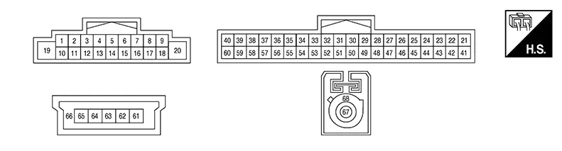
PHYSICAL VALUES
|
Terminal (Wire color) |
Description |
Condition |
Reference value (Approx.) |
|||
|---|---|---|---|---|---|---|
|
+ |
– |
Signal name |
Input/Output |
Ignition switch |
Operation |
|
|
2 (LA/BR) |
3 (LA/SB) |
Sound signal front door speaker |
Output |
ON |
Sound output |
 |
|
4 (LG) |
5 (P) |
Sound signal rear speaker LH |
Output |
ON |
Sound output |
|
|
8 (LA/SB) |
— |
CAN-High |
Input/Output |
— |
— |
— |
|
11 (LA/B) |
12 (LA/R) |
Sound signal front door speaker |
Output |
ON |
Sound output |
|
|
13 (G) |
14 (R) |
Sound signal rear speaker RH |
Output |
ON |
Sound output |
|
|
17 (LA/V) |
— |
CAN-Low |
Input/Output |
— |
— |
— |
|
19 (P) |
Ground |
Battery power supply |
Input |
OFF |
— |
Battery voltage |
|
20 (B) |
Ground |
— |
— |
— |
— |
0 V |
|
21 (LA/LG) |
— |
AV communication low |
Input/Output |
— |
— |
— |
|
22 (LA/LG) |
— |
AV communication low |
Input/Output |
— |
— |
— |
|
29 (B) |
Ground |
Camera detect ground |
— |
ON |
— |
0 V |
|
34 (LG) |
Ground |
MIC VCC |
Output |
ON |
— |
5 V |
|
35 (G) |
Ground |
AUX jack audio signal LH |
Input |
ON |
Received audio signal (AUX input) |
|
|
36 (Y) |
Ground |
AUX ground |
— |
ON |
— |
0 V |
|
39 (R) |
Ground |
Camera power supply |
Output |
ON |
Camera image displayed |
6.0 V |
|
Except for above |
0 V |
|||||
|
40 (B) |
60 (Shield) |
Camera image signal |
Input |
ON |
Camera image displayed |
 |
|
41 (LA/SB) |
— |
AV communication high |
Input/Output |
— |
— |
— |
|
42 (LA/SB) |
— |
AV communication high |
Input/Output |
— |
— |
— |
|
43 (Y) |
— |
HF/VR mode change |
— |
— |
— |
— |
|
53 (V) |
54 (Shield) |
Microphone signal |
Input |
ON |
While speaking into microphone. |
|
|
55 (L) |
Ground |
AUX jack audio signal RH |
Input |
ON |
Received audio signal (AUX input) |
|
|
56 (Shield) |
— |
AUX signal shield |
— |
— |
— |
— |
|
59 (W) |
Ground |
Camera ground |
— |
ON |
— |
0 V |
|
61 (Y) |
— |
USB ground |
— |
— |
— |
— |
|
63 (L) |
— |
USB D+ signal |
— |
— |
— |
— |
|
64 (G) |
— |
USB D− signal |
— |
— |
— |
— |
|
65 (R) |
— |
V BUS signal |
— |
— |
— |
— |
|
66 (Shield) |
— |
USB shield |
— |
— |
— |
— |
|
67 (B) |
Ground |
AM/FM antenna signal |
Input |
ON |
AV control unit ON, FM-AM selected. |
5.0 V |
|
68 (Shield) |
— |
AM/FM antenna shield |
— |
— |
— |
— |
Fail Safe
Fail safe
|
DTC |
AV control unit operation in fail-safe mode |
|---|---|
|
B1339–8F |
Rear view camera is inoperative |
|
U0079–00 |
CAN communication does not function |
|
U1300–01 |
AV communication is inoperative |
|
U2148–87 |
CAN communication is inoperative |
|
U214E–87 |
CAN communication is inoperative |
|
U214F–87 |
CAN communication is inoperative |
|
U215B–87 |
CAN communication is inoperative |
Dtc Inspection Priority Chart
DTC Inspection Priority Chart
If multiple DTCs are detected simultaneously, check them one by one depending on the following DTC inspection priority chart:
|
Priority |
Detected items (DTC) |
|---|---|
|
1 |
|
|
2 |
B1339–8F: Rear camera connection |
Dtc Index
DTC Index
|
CONSULT Display |
Reference Page |
|---|---|
|
B1339–8F: Rear camera connection |
DTC Description |
|
U0079–00: Control module comm Bus G Off |
DTC Description |
|
U1300–01: AV communication circuit |
DTC Description |
|
U2148–87: CAN comm err (brake control unit) |
DTC Description |
|
U214E–87: CAN comm err (combination meter) |
DTC Description |
|
U214F–87: CAN comm err (BCM) |
DTC Description |
|
U215B–87: CAN comm err (IPDM E/R) |
DTC Description |
Other materials:
B0012-55 Active Vent
Dtc Description
DTC Description
DTC DETECTION LOGIC
DTC No.
CONSULT screen items
(Trouble diagnosis
content)
DTC Detection Condition
...
Hazard Switch
Component Inspection
Component Inspection
CHECK HAZARD SWITCH
Ignition switch OFF.
Disconnect hazard switch connector.
Check continuity between hazar ...
B203d-14 Inside Antenna
Dtc Description
DTC Description
DTC DETECTION LOGIC
DTC No.
CONSULT screen items
(Trouble diagnosis content)
DTC detecting condition
...