Nissan Sentra B18 (2020-2025) Service Manual: Diagnosis System (av Control Unit)
Description
Description
The AV control unit on board diagnosis performs the functions listed in the table below:
|
Mode |
Description |
|
|---|---|---|
|
Self Diagnosis |
|
|
|
Confirmation/Adjustment |
Display Diagnosis |
The following check functions are available:
|
|
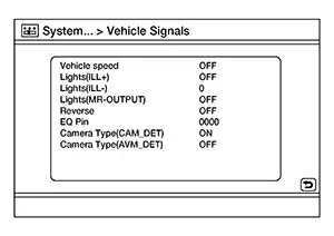
Nissan Sentra Vehicle Signals |
Diagnosis of signals can be performed for Nissan Sentra vehicle speed, lights, reverse, ignition, EQ pin, camera type and DC offset. |
|
|
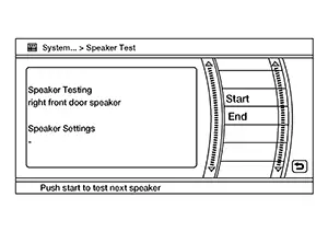
Speaker Test |
Individual speakers can be checked. |
|
|
Error History |
Displays error name and error count. |
|
|
Camera System |
The following functions are available:
|
|
|
AV COMM Diagnosis |
AV communication information is displayed. |
|
|
Delete Unit Connection Log |
Erase the connection history of unit. |
|
|
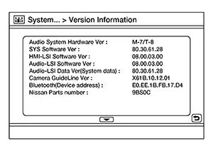
Version Information |
Version information of the AV control unit is displayed. |
|
|
Initialize Setting |
System memory can be erased. |
|
Perform CONSULT diagnosis if the AV control unit on board diagnosis does not start, or the screen does not display anything.
On Board Diagnosis Function
On Board Diagnosis Function
METHOD OF STARTING
AV Control Unit Self Diagnosis
-
Ignition switch ON.
-
Audio system OFF.
-
While pressing the MENU button, turn the VOL dial clockwise or counterclockwise for 40 clicks or more. Shifting from current screen to previous screen is performed by pressing BACK button.
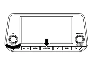
-
The trouble diagnosis initial screen is displayed, and “Self Diagnosis” and “Confirmation/Adjustment” can be selected.
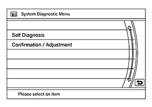
SELF-DIAGNOSIS MODE
-
Start the self-diagnosis function and select “Self Diagnosis”.
-
Self-diagnosis subdivision screen is displayed, and the self-diagnosis mode starts.
-
The bar graph visible on the center of the self-diagnosis subdivision screen indicates progress of the trouble diagnosis.
-
-
Diagnosis results are displayed after the self-diagnosis is completed. The unit names and the connection lines are color-coded according to the diagnostic results.
Note:Diagnosis results
Unit
Connection line
Normal
Green
Green
Connection malfunction
Gray
Yellow
Unit malfunction Note
Red
Green

Control Unit (AV control unit) is displayed in red.
-
Replace AV control unit if “Self-Diagnosis did not run because of a control unit malfunction” is indicated. The symptom is AV control unit internal error. Refer to Removal and Installation.
-
If multiple errors occur at the same time for a single unit, the screen switch colors are determined according to the following order of priority: red > gray.
-
Detection Range of Self-diagnosis Mode
-
The self-diagnosis mode allows the technician to diagnose the connection in the communication line between AV control unit and each unit and the internal operation of the AV control unit.
-
Because the start condition of diagnosis function is a switch operation, the on board diagnosis function cannot be started up if any malfunction is detected in the AV control unit switches.
SELF-DIAGNOSIS RESULTS
Only Unit Part Is Displayed In Red
|
Screen switch |
Description |
Possible malfunction location / Action to take |
|---|---|---|
|
Head Unit |
Malfunction is detected in AV control unit power supply and ground circuits. |
Check AV control unit power supply and ground circuits. Refer to Diagnosis Procedure. When no malfunction is detected in those circuits, replace AV control unit. Refer to Removal and Installation. |
|
Meter |
Malfunction is detected in combination meter power supply and ground circuits. |
Check combination meter power supply and ground circuits. Refer to Diagnosis Procedure. When no malfunction is detected in those circuits, replace combination meter. Refer to Removal and Installation. |
A Connecting Cable Between Units Is Displayed In Yellow
|
Area with yellow connection lines |
Description |
Possible malfunction location / Action to take |
|---|---|---|
|
Head unit ⇔ Meter |
Combination meter AV communication connection malfunction detected. |
AV communication circuits between AV control unit and combination meter. |
CONFIRMATION/ADJUSTMENT MODE
-
Start the diagnosis function and select “Confirmation/Adjustment”. The confirmation/adjustment mode indicates where each item can be checked or adjusted.
-
Select each switch on the “Confirmation/Adjustment Mode” screen to display the relevant trouble diagnosis screen. Touch the “Back” to return to the initial Confirmation/Adjustment Mode screen.
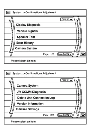
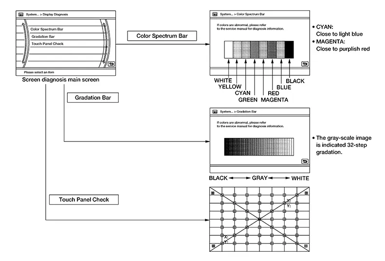
Display Diagnosis
Confirmation of the AV control unit screen operation.
Nissan Sentra Vehicle Signals
A comparison check can be made of each actual vehicle signal and the signals recognized by the system.
Speaker Test
Test tones can be generated to each speaker.
Error History
The self diagnosis results are judged depending on whether any error occurs from when Self Diagnosis is selected until the self diagnosis results are displayed.
However, the diagnosis results are judged normal if an error has occurred before the ignition switch is turned ON and then no error has occurred until the self diagnosis start. Check the Error Record to detect any error that may have occurred before the self diagnosis start because of this situation.
The frequency of occurrence is displayed in a count up manner. The actual count up method differs depending on the error item.
Count up method A
-
The counter is set to 40 if an error occurs. 1 is subtracted from the counter if the condition is normal at a next ignition ON cycle.
-
The counter lower limit is 1. The counter can be reset (no error record display) with the Delete log switch.
Count up method B
-
The counter increases by 1 if an error occurs when ignition switch is ON. The counter will not decrease even if the condition is normal at the next ignition ON cycle.
-
The counter upper limit is 50. Any counts exceeding 50 are ignored. The counter can be reset (no error record display) with the Delete log switch.
|
Display type of occurrence frequency |
Error history display item |
|---|---|
|
Count up method A |
AV communication line, control unit (AV) |
|
Count up method B |
Other than the above |
Error item
Some error items may be displayed simultaneously according to the cause. If some error items are displayed simultaneously, the detection of the cause can be performed by the combination of display items
|
Error item |
Description |
Possible cause |
|---|---|---|
|
CONTROL UNIT (AV) |
AV communication circuit initial diagnosis malfunction is detected. |
Replace the AV control unit if the malfunction occurs constantly. Refer to Removal and Installation |
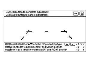
Camera System
This mode is used to adjust the guide line display position of the rear view camera.
AV COMM Diagnosis
-
The error counter displays “OK” if any malfunction was not detected in the past and displays “0” if a malfunction is detected. It increases by 1 if the condition is normal at the next ignition switch ON cycle. The upper limit of the counter is 39.
-
The error counter is erased if “Reset” is pressed.
|
Items |
Status (Current) |
Counter (Past) |
|---|---|---|
| BUS OFF | OK / ??? | OK / 0 Â 39 |
"???" indicates UNKWN.
Delete Unit Connection Log
Deletes any unit connection records and error records from the AV control unit memory.

Version Information
Displays audio system version numbers.
Initialize Settings
Deletes data stored from the AV control unit.
Consult Function
CONSULT Function
CONSULT FUNCTIONS
CONSULT performs the following functions via communication with the AV control unit:
|
Diagnosis Mode |
CGW Status |
Description |
||
|---|---|---|---|---|
|
Restricted Mode |
Diag Test Mode |
Open Mode |
||
|
ECU Identification |
Display |
Display |
Display |
The AV control unit part number is displayed. |
|
Self Diagnostic Result |
Display |
Display |
Display |
The AV control unit self diagnostic results are displayed. |
|
CGW Information |
Display |
Display |
Display |
|
|
Data Monitor |
Display |
Display |
Display |
The AV control unit input/output data is displayed in real time. |
|
Work Support |
Non-display |
Non-display |
Display |
Save or write VIN information. |
|
Configuration |
Display |
Display |
Display |
|
|
CAN Diag Support Monitor* |
Display |
Display |
Display |
Note:
The mode is indicated, but not monitored. |
|
Network-DTC* |
Display |
Display |
Display |
Display network DTC which AV control unit memorizes when performing "Diagnosis (All System)". |
*: Displays when performing "Diagnosis (All System)".
ECU IDENTIFICATION
The part number of AV control unit is displayed.
SELF DIAGNOSTIC RESULT
Refer to DTC Index.
CGW INFORMATION
Displays the diagnosis mode which a user can perform in Diag Test mode/Open Mode by switching the CGW status from Restricted mode to Diag Test Mode/Open Mode.
For the method of switching CAN Gateway status, refer to CONSULT Function.
DATA MONITOR
Note:
The following table includes information (items) inapplicable to this Nissan Sentra vehicle. For information (items) applicable to this vehicle, refer to CONSULT display items.
|
Monitor Item [Unit] |
Description |
|---|---|
|
Sunload sensor [On/Off] |
Indicates sunload sensor signal received from A/C auto amp. on CAN communication line. |
|
Parking brake [On/Off] |
Indicates condition of parking brake signal for the AV control unit. |
|
IGN SIG [On/Off] |
Indicates condition of ignition signal. |
|
Auto ACC [On/Off] |
Indicates condition of auto ACC signal. |
|
ACC [On/Off] |
Indicates condition of ACC signal. |
|
Aux IN 1 [Con/No con] |
Indicates connection condition of Aux in jack. |
|
Aux IN 2 [Con/No con] |
Indicates connection condition of USB. |
|
REV SIG [On/Off] |
Indicates condition of reverse signal received from transmission range switch. |
|
ILLUM SIG [On/Off] |
Indicates condition of illumination signal for the AV control unit. |
|
Illumination Control[On/Off] |
Indicates condition of illumination control signal for the AV control unit. |
WORK SUPPORT
|
Test item |
Description |
|---|---|
|
SAVE VIN DATA |
Allows the reading of VIN data written in AV control unit to store the specification in CONSULT. |
|
WRITE VIN (SAVED DATA) |
Allows the writing of the VIN data stored in CONSULT into the AV control unit. |
|
WRITE VIN (MANUAL INPUT) |
Allows the writing of the VIN data into the AV control unit by hand. |
CONFIGURATION
Configuration has three functions as follows.
|
Function |
Description |
|
|---|---|---|
|
Read/Write Configuration |
Before Replace ECU |
Allows the reading of Nissan Sentra vehicle specification written in AV control unit to store the specification in CONSULT. |
|
After Replace ECU |
Allows the writing of the Nissan Sentra vehicle information stored in CONSULT into the AV control unit. |
|
|
Manual Configuration |
Allows the writing of the Nissan Sentra vehicle specification into the AV control unit by hand. |
|
Other materials:
P0746-00 Pressure Control Solenoid a
Dtc Description
DTC Description
DTC DETECTION LOGIC
DTC
CONSULT screen terms
(Trouble diagnosis
content)
DTC detection
conditi ...
P27a6-00 Electric Oil Pump
Dtc Description
DTC Description
DTC DETECTION LOGIC
DTC
CONSULT screen terms
(Trouble diagnosis
content)
DTC detection
conditi ...
B203d-14 Inside Antenna
Dtc Description
DTC Description
DTC DETECTION LOGIC
DTC No.
CONSULT screen items
(Trouble diagnosis content)
DTC detecting condition
...