Nissan Sentra B18 (2020-2025) Service Manual: Dtc/circuit Diagnosis
Power Supply and Ground Circuit
Av Control Unit
Diagnosis Procedure
Diagnosis Procedure
-
CHECK FUSE
-
Check that the following fuse is not blown:
Terminal No.
Signal name
Fuse No.
Capacity
19
Battery power supply
40
20 A
Is the fuse blown?
YES >>Replace the blown fuse after repairing the affected circuit.
NO >>GO TO 2.
-
-
CHECK POWER SUPPLY CIRCUIT
-
-
Ignition switch OFF.
-
Disconnect AV control unit connector.
-
Check voltage between AV control unit connector and ground.
AV control unit
—
Condition
Voltage
(Approx.)
Connector
Terminal
M92
19
Ground
Ignition switch: OFF
Battery voltage
-
Is the inspection result normal?
YES >>GO TO 3.
NO >>Repair or replace harness or connectors.
-
-
CHECK GROUND CIRCUIT
-
-
Disconnect AV control unit connector.
-
Check continuity between AV control unit connector and ground.
AV control unit
—
Continuity
Connector
Terminal
M92
20
Ground
Yes
M93
29
-
Is the inspection result normal?
YES>>Inspection End.
NO>>Repair or replace harness or connectors.
-
Rear View Camera Image Signal Circuit
Diagnosis Procedure
Diagnosis Procedure
-
CHECK CAMERA POWER SUPPLY CIRCUIT CONTINUITY
-
-
Ignition switch OFF.
-
Disconnect AV control unit connector and rear view camera connector.
-
Check continuity between AV control unit connector and rear view camera connector.
AV control unit
Rear view camera
Continuity
Connector
Terminal
Connector
Terminal
M93
39
B30
1
Yes
-
Check continuity between AV control unit connector and ground.
AV control unit
—
Continuity
Connector
Terminal
M93
39
Ground
No
-
Is inspection result normal?
YES >>GO TO 2.
NO >>Repair or replace harness or connectors.
-
-
CHECK CAMERA POWER SUPPLY VOLTAGE
-
-
Connect AV control unit connector and rear view camera connector.
-
Ignition switch ON.
-
Shift the selector lever to R (reverse).
-
Check voltage between AV control unit connector and ground.
AV control unit
(−)
Condition
Voltage
(Approx.)
(+)
Connector
Terminal
M93
39
Ground
Selector lever is in “R�.
6.0 V
-
Is inspection result normal?
YES >>GO TO 3.
NO >>Replace AV control unit. Refer to Removal and Installation.
-
-
CHECK CAMERA IMAGE SIGNAL CIRCUIT CONTINUITY
-
-
Ignition switch OFF.
-
Disconnect AV control unit connector and rear view camera connector.
-
Check continuity between AV control unit connector and rear view camera connector.
AV control unit
Rear view camera
Continuity
Connector
Terminal
Connector
Terminal
M93
40
B30
3
Yes
-
Check continuity between AV control unit connector and ground.
AV control unit
—
Continuity
Connector
Terminal
M93
40
Ground
No
-
Is inspection result normal?
YES >>GO TO 4.
NO >>Repair or replace harness or connectors.
-
-
CHECK CAMERA GROUND CIRCUIT CONTINUITY
-
Check continuity between AV control unit connector and rear view camera connector.
AV control unit
Rear view camera
Continuity
Connector
Terminal
Connector
Terminal
M93
59
B30
2
Yes
Is inspection result normal?
YES >>GO TO 5.
NO >>Repair or replace harness or connectors.
-
-
CHECK CAMERA IMAGE SIGNAL
-
-
Connect AV control unit connector and rear view camera connector.
-
Ignition switch ON.
-
Shift the selector lever to R (reverse).
-
Check signal between AV control unit connector and ground.
AV control unit
(−)
Condition
Reference value
(+)
Connector
Terminal
M93
40
Ground
Camera image displayed.
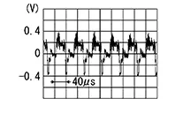
-
Is inspection result normal?
YES >>Replace AV control unit. Refer to Removal and Installation.
NO >>Replace rear view camera. Refer to Removal and Installation.
-
Other materials:
Engine cooling system
The engine cooling system of the Nissan Sentra is factory-filled with a pre-diluted
mixture consisting of 50% Genuine NISSAN Long Life Antifreeze/Coolant (blue) and
50% water. This formulation is designed to provide reliable, year-round antifreeze
protection and effective engine cooling perfor ...
Power Outlet. Preparation. Preparation. Special Service Tool
Preparation. Special Service Tool
Special Service Tool
Special Service Tool
The actual shape of the tools may differ from those
illustrated here.
Tool number
(TechMate No.)
Tool name
&nb ...
Magnet Clutch
Component Function Check
Component Function Check
CHECK MAGNET CLUTCH OPERATION
Perform auto active test of IPDM E/R. Refer to CONSULT Function (IPDM E/R).
Does it operate normally?
YES >>
Inspection End.
NO > ...