Nissan Sentra Service Manual: Dtc/circuit diagnosis
U1000 can comm circuit
Description
Refer to LAN-7, "CAN COMMUNICATION SYSTEM : System Description".
Dtc logic
DTC DETECTION LOGIC
NOTE:
U1000 can be set if a module harness was disconnected and reconnected, perhaps during a repair. Confirm that there are actual CAN diagnostic symptoms and a present DTC by performing the Self Diagnostic Result procedure.
| CONSULT Display | DTC Detection Condition | Possible Cause |
| CAN COMM CIRCUIT [U1000] | When any listed module cannot communicate with CAN communication signal continuously for 2 seconds or more with ignition switch ON | In CAN communication system, any item (or
items) of the following listed below is malfunctioning.
|
Diagnosis procedure
1. PERFORM SELF DIAGNOSTIC RESULT
- Turn ignition switch ON and wait for 2 second or more.
- Check “SELF- DIAG RESULTS”.
Is “CAN COMM CIRCUIT” displayed? YES >> Perform CAN Diagnosis as described in DIAGNOSIS section of CONSULT Operation Manual.
NO >> Refer to GI-39, "Intermittent Incident".
U1010 control unit (can)
Dtc logic
DTC DETECTION LOGIC

Diagnosis procedure
1.REPLACE BCM
When DTC “U1010” is detected, replace BCM.
>> Replace BCM. Refer to BCS-73, "Removal and Installation".
U0415 vehicle speed
Dtc logic
DTC DETECTION LOGIC
NOTE:
- If DTC U0415 is displayed with DTC U1000, first perform the trouble diagnosis for DTC U1000. Refer to BCS-63, "DTC Logic".
- If DTC U0415 is displayed with DTC U1010, first perform the trouble diagnosis for DTC U1010. Refer to BCS-64, "DTC Logic".
| CONSULT Display | DTC Detection Condition | Probable Cause |
| VDC CAN CIR2 [U0415] | When the vehicle speed signal received from the ABS actuator and electric unit (control unit) remains abnormal for 2 seconds or more. |
|
DTC CONFIRMATION PROCEDURE
1. DTC CONFIRMATION
- Erase the DTC
- Turn ignition switch OFF
- Perform Self Diagnostic Result of BCM with CONSULT, after the ignition switch has been turned ON for 2 seconds or more.
Is any DTC detected? YES >> Refer to BCS-65, "Diagnosis Procedure".
NO >> Inspection End.
Diagnosis procedure
1. ABS ACTUATOR AND ELECTRIC UNIT (CONTROL UNIT) SELF DIAGNOSTIC RESULT
Perform Self Diagnostic Result of ABS with CONSULT. Refer to BRC-31, "CONSULT Function (ABS)".
Is any DTC detected? YES >> Perform the trouble diagnosis related to the detected DTC. Refer to BRC-43, "DTC Index".
NO >> GO TO 2.
2. CHECK ABS ACTUATOR AND ELECTRIC UNIT (CONTROL UNIT) POWER SUPPLY AND GROUND CIRCUIT
Check ABS actuator and electric unit (control unit) power and ground. Refer to BRC-62, "Diagnosis Procedure".
Is the inspection result normal? YES >> GO TO 3.
NO >> Repair or replace harness or connectors.
3. COMBINATION METER SELF DIAGNOSTIC RESULT
Perform Self Diagnostic Result of METER M&A with CONSULT. Refer to MWI-17, "CONSULT Function (METER/M&A)".
Is any DTC detected? YES >> Perform the trouble diagnosis related to the detected DTC. Refer to MWI-26, "DTC Index".
NO >> Refer to GI-39, "Intermittent Incident".
B2562 low voltage
Dtc logic
DTC DETECTION LOGIC
| CONSULT Display | DTC Detection Condition | Possible Cause |
| LOW VOLTAGE [B2562] | When the power supply voltage to BCM remains less than 8.8 V for 120 seconds or more |
|
DTC CONFIRMATION PROCEDURE
1. DTC CONFIRMATION
- Erase DTC.
- Turn ignition switch OFF.
- Perform the Self Diagnostic Result of BCM with CONSULT, after the ignition switch has been turned ON for 120 seconds or more.
Is any DTC detected? YES >> Refer to BCS-66, "Diagnosis Procedure".
NO >> Inspection End.
Diagnosis procedure
1. CHECK BATTERY VOLTAGE
Check battery voltage.
Is battery voltage less than 8.8V? YES >> Charge battery and retest. Refer to CHG-14, "Work Flow (With EXP-800 NI or GR8-1200 NI)" or CHG-17, "Work Flow (Without EXP-800 NI or GR8-1200 NI)".
NO >> GO TO 2.
2. CHECK POWER SUPPLY AND GROUND CIRCUIT
Check BCM power supply and ground circuit. Refer to BCS-67, "Diagnosis Procedure".
Is the inspection result normal? YES >> GO TO 3.
NO >> Repair or replace harness or connectors.
3. BCM SELF DIAGNOSTIC RESULT
Perform Self Diagnostic Result of BCM with CONSULT. Refer to BCS-24, "BCM : CONSULT Function (BCM - BCM)".
Is DTC B2562 CRNT? YES >> Replace BCM. Refer to BCS-73, "Removal and Installation".
NO >> Refer to GI-39, "Intermittent Incident".
Power supply and ground circuit
Diagnosis procedure
Regarding wiring diagram information, refer to bcs-51, "wiring diagram".
1.Check fuses and fusible link
Check that the following fuses and fusible link are not blown.

Is the fuse blown? Yes >> replace the blown fuse or fusible link after repairing the affected circuit.
No >> go to 2.
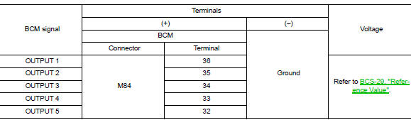
2.Check power supply circuit
- Disconnect BCM connector M85.
- Check voltage between bcm connector m85 and ground.
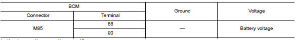
Is the inspection result normal? Yes >> go to 3.
No >> repair harness or connector.
3.Check ground circuit
Check continuity between BCM connector M85 and ground.
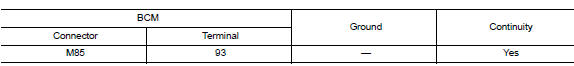
Is the inspection result normal? Yes >> inspection end.
No >> repair harness or connector.
Combination switch input circuit
Diagnosis procedure
Regarding Wiring Diagram information, refer to BCS-51, "Wiring Diagram".
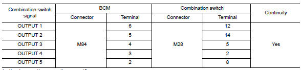
1.Check input 1 - 5 circuit for open
- Turn ignition switch off.
- Disconnect bcm and combination switch connectors.
- Check continuity between BCM connector and combination switch connector.
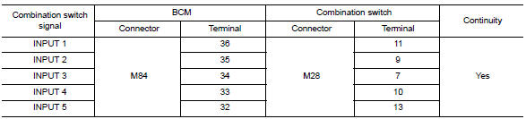
Is the inspection result normal? Yes >> go to 2.
No >> repair harness or connectors.
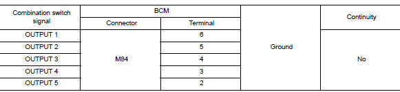
2.Check input 1 - 5 circuit for short
Check for continuity between bcm connector and ground.
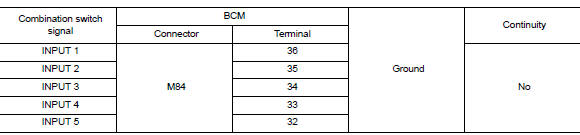
Is the inspection result normal? YES >> Repair harness or connectors.
NO >> GO TO 3.
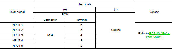
3.Check bcm output voltage
- Connect bcm connector.
- Check voltage between bcm connector and ground.
Is the inspection result normal? Yes >> replace combination switch.
No >> replace bcm. Refer to bcs-73, "removal and installation".
Combination switch output circuit
Diagnosis procedure
Regarding wiring diagram information, refer to bcs-51, "wiring diagram".
1.Check output 1 - 5 circuit for open
- Turn ignition switch off.
- Disconnect bcm and combination switch connectors.
- Check continuity between BCM connector and combination switch connector.
Is the inspection result normal? Yes >> go to 2.
No >> repair harness or connectors.
2.Check output 1 - 5 circuit for short
Check for continuity between BCM connector and ground.
Is the inspection result normal? YES >> Repair harness or connectors.
NO >> GO TO 3.
3.Check bcm input signal
- Connect bcm and combination switch connectors.
- Turn ON any switch in the system that is malfunctioning.
- Check voltage between bcm connector and ground.
Is the inspection result normal? Yes >> replace bcm. Refer to bcs-73, "removal and installation".
No >> replace combination switch.
 Basic inspection
Inspection and adjustment
Additional service when replacing control unit (bcm)
ADDITIONAL SERVICE WHEN REPLACING CONTROL UNIT (BCM) : Description
Before replacement
When replacing bcm, save or pri ...
 Symptom diagnosis
Combination switch system symptoms
Symptom Table
Perform the data monitor of consult to check for any malfunctioning
item.
Check the malfunction combinations.
Identify the malfunct ...
Other materials:
P0999 Shift solenoid F
DTC Logic
DTC DETECTION LOGIC
DTC
CONSULT screen terms
(Trouble diagnosis content)
DTC detection condition
Possible causes
P0999
SHIFT SOLENOID F
(Shift Solenoid F Control Circuit
High)
The TCM low brake solenoid valve current
monitor reading is 200 mA or ...
Diagnosis system (BCM) (without intelligent key system)
Common item
Common item : consult function (bcm - common item)
APPLICATION ITEM
CONSULT performs the following functions via CAN communication with BCM.
Direct Diagnostic Mode
Description
ECU identification
The BCM part number is displayed.
Self Diagnostic Result
...
Service data and specifications
(sds)
General Specification
Drive Belt
Spark Plug
*:Always check with the Parts Department for the latest parts information.
Exhaust Manifold
Camshaft
VALVE LIFTER
VALVE CLEARANCE
*: Approximately 80В°C (176В°F)
AVAILABLE VALVE LIFTER
*:Always check with the P ...
