Nissan Sentra Service Manual: P0999 Shift solenoid F
DTC Logic
DTC DETECTION LOGIC
| DTC | CONSULT screen terms (Trouble diagnosis content) | DTC detection condition | Possible causes |
| P0999 | SHIFT SOLENOID F (Shift Solenoid F Control Circuit High) | The TCM low brake solenoid valve current
monitor reading is 200 mA or less continuously
for 200 msec or more under the following diagnosis
conditions: Diagnosis conditions
|
|
DTC CONFIRMATION PROCEDURE
1.PREPARATION BEFORE WORK
If another “DTC CONFIRMATION PROCEDURE” occurs just before, turn ignition switch OFF and wait for at least 10 seconds, then perform the next test.
>> GO TO 2.
2.CHECK DTC DETECTION
- Start the engine.
- Shift the selector lever to “D” position and wait for 5 seconds or more.
- Check the first trip DTC.
Is “P0999” detected? YES >> Go to TM-212, "Diagnosis Procedure".
NO >> INSPECTION END
Diagnosis Procedure
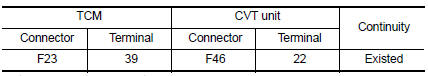
1.CHECK CIRCUIT BETWEEN TCM AND CVT UNIT
- Turn ignition switch OFF.
- Disconnect TCM connector and CVT unit connector.
- Check continuity between TCM harness connector terminal and CVT unit harness connector terminal.
 Is the inspection
result normal?
YES >> GO TO 2.
NO >> Repair or replace malfunctioning parts.
2.CHECK LOW BRAKE SOLENOID VALVE
Check low brake solenoid valve. Refer to TM-213, "Component Inspection".
Is the inspection result normal? YES >> Check intermittent incident. Refer to GI-39, "Intermittent Incident".
NO >> Repair or replace malfunctioning parts.
Component Inspection
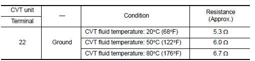
1.CHECK LOW BRAKE SOLENOID VALVE
Check resistance between CVT unit connector terminal and ground.
 Is the inspection
result normal?
YES >> INSPECTION END
NO >> There is a malfunction of low brake solenoid valve. Replace transaxle assembly. Refer to TM-283, "Removal and Installation".
 P0998 Shift solenoid F
DTC Logic
DTC DETECTION LOGIC
DTC
CONSULT screen terms
(Trouble diagnosis content)
DTC detection condition
Possible causes
P0998
SHIFT SOLENOID F
(Shift Solenoid F ...
 P099B Shift solenoid G
DTC Logic
DTC DETECTION LOGIC
DTC
CONSULT screen terms
(Trouble diagnosis content)
DTC detection condition
Possible causes
P099B
SHIFT SOLENOID G
(Shift Solenoid G ...
Other materials:
Precaution
Precaution for Supplemental Restraint System (SRS) "AIR BAG" and "SEAT
BELT PRE-TENSIONER"
The Supplemental Restraint System such as “AIR BAG” and “SEAT BELT PRE-TENSIONER”,
used along
with a front seat belt, helps to reduce the risk or severity of injur ...
Wiring diagram
Display audio without bose
Wiring diagram
...
U0155 Lost communication (IPC)
DTC Logic
DTC DETECTION LOGIC
DTC
CONSULT screen terms
[Trouble diagnosis content]
DTC detection condition
Possible causes
U0155
LOST COMM (IPC)
[Lost Communication With Instrument
Panel Cluster (IPC)
Control Module]
When the ignition switch is ON, TCM is ...
