Nissan Sentra B18 (2020-2025) Service Manual: Driver Side
Exploded View
Exploded View
POWER SEAT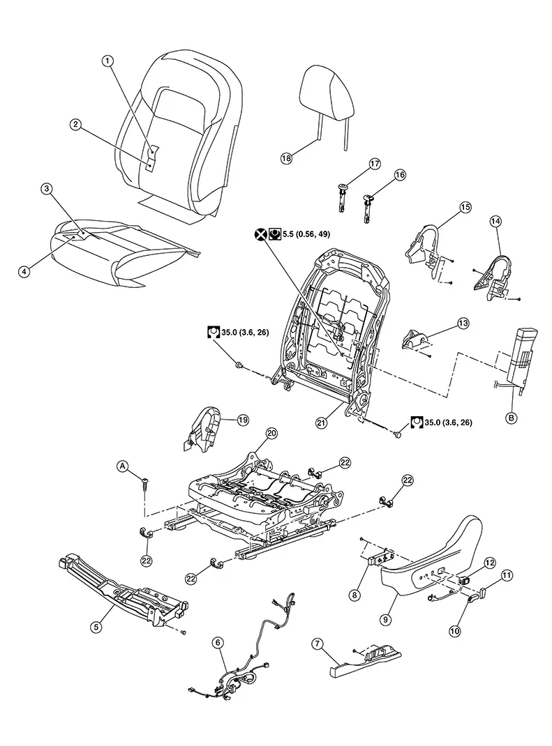
|
1. |
Seatback trim |
2. |
Seatback pad |
3. |
Seat cushion trim |
|
4. |
Seat cushion pad |
5. |
Seat cushion bracket |
6. |
Seat harness |
|
7. |
Slide cover (LH) |
8. |
Power seat switch |
9. |
Seat cushion outside finisher (LH) |
|
10. |
Seat slide knob |
11. |
Seat recline knob |
12. |
Lumbar support switch |
|
13. |
Slide cover (RH) |
14. |
Seat cushion inside finisher (LH) |
15. |
Seat cushion inside finisher (RH) |
|
16. |
Headrest holder (locked) |
17. |
Headrest holder (free) |
18. |
Headrest |
|
19. |
Seat cushion outside finisher (RH) |
20. |
Seat cushion frame assembly |
21. |
Seat back frame assembly |
|
22. |
Slide covers |
A. |
Refer to Removal and Installation. |
B. |
Side air bag module (not serviceable) |
|
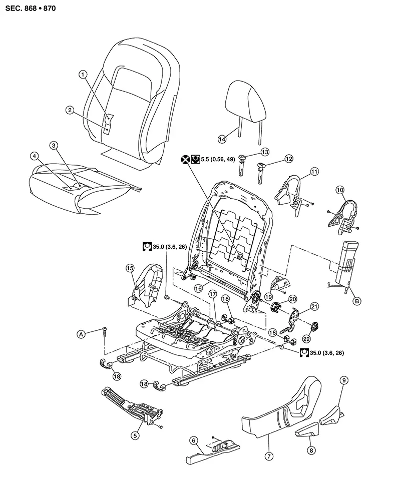
1. |
Seatback trim |
2. |
Seatback pad |
3. |
Seat cushion trim |
|
4. |
Seat cushion pad |
5. |
Seat cushion bracket |
6. |
Seat track finisher (LH) |
|
7. |
Seat cushion outside finisher (LH) |
8. |
Lift lever |
9. |
Recline lever finisher |
|
10. |
Seat cushion inside finisher (LH) |
11. |
Seat cushion inside finisher (RH) |
12. |
Headrest holder (locked) |
|
13. |
Headrest holder (free) |
14. |
Headrest |
15. |
Seat cushion outside finisher (RH) |
|
16. |
Seat back frame assembly |
17. |
Seat cushion frame assembly |
18. |
Slide covers |
|
19. |
Seat track finisher (RH) |
20. |
Reclining lever escutcheon inner |
21. |
Reclining lever bracket |
|
22. |
Reclining lever escutcheon outer |
A. |
Refer to Removal and Installation. |
B. |
Side air bag module (not serviceable) |
Disassembly and Assembly
Disassembly and Assembly
SEATBACK ASSEMBLY
Warning:
Do not leave any objects (screwdrivers, tools, etc.) on the seat during seatback repair. It can lead to personal injury if the side air bag should accidentally deploy.
CAUTION:
-
Before servicing, ignition switch OFF, disconnect both battery terminals and wait at least three minutes.
-
Handle the side air bag module carefully. During disassembly, always hold the side air bag module, do not let it hang by the wire harness.
-
Always work from the side or back of the seatback assembly, do not work in front of seat.
-
Do not use air tools or electric tools for servicing the seat assembly.
-
Replace the side air bag module if it has been dropped or sustained an impact.
-
Do not insert any objects into the side air bag module.
-
Do not attempt to disassemble the side air bag module.
-
Do not expose the side air bag module to temperatures exceeding 93°C (200°F).
-
Do not expose the side air bag module to any oil, grease, detergent or water.
-
During disassembly, do not damage the seatback board, chutes, connectors, retainers, clips, module harness or the side air bag module.

If the Nissan Sentra vehicle has been involved in a collision and the side air bag module has deployed, the seat assembly must be replaced.
Disassembly
Remove the front seat assembly. Refer to Removal and Installation - Seat Assembly.
Remove the headrest. Refer to Exploded View.
Release the
lower seatback trim retainer straps (D) from the bottom side of the
seat frame assembly. 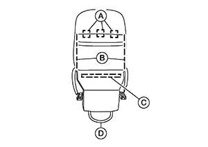
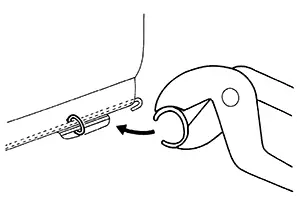
Using suitable tool, release J-hook (C).
Unzip the seatback zippers (B).
Remove hog rings (A).
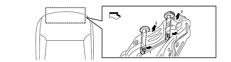
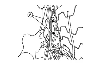
Release the
headrest holder locks in order shown and remove the headrest
holders.
|
|
: Front |
CAUTION:
Before removing/installing the headrest holder, check its orientation (front/rear and right/left).
Disconnect the harness connector from the front seat heater (if equipped).
Using
suitable tool, release heated seat harness retainers (if
equipped) Note:
Take note of harness routing and attachment location for correct installation.
Using
suitable tool, release the side air bag module harness
retainers. Note:
Take note of harness routing and attachment location for accurate installation.
Release
J-hooks (A) from the seat frame assembly. 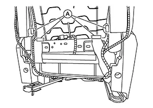
Remove and
discard the two side air bag module nuts (A).
CAUTION:
Do not reuse the side air bag module nuts.
Release the side air bag module studs from the seatback frame and lift the seatback trim and seatback pad as an assembly from the seat frame assembly.
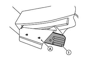
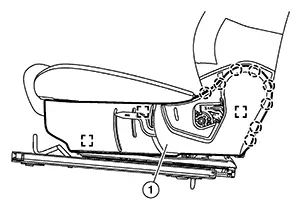
Pull the
side air bag module (1) out of the chute (A) and remove from the
seatback trim.
CAUTION:
-
Replace the seat if side air bag module has been dropped or sustained an impact.
-
Do not strike the side air bag module.
Remove the
hog rings and separate the seatback trim from the seatback
pad. 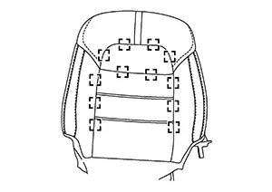
|
|
: Hog ring |
Remove all pieces of hog rings and discard them.
Assembly
Assembly is in the reverse order of disassembly.
CAUTION:
-
When installing the front side air bag module, make sure the inner cloth (reinforcement cloth) is not caught in a bolt hole.
-
Do not reuse the front side air bag module nuts.
-
Do not tighten the front side air bag module nuts twice (prevent improper torque).
-
Do not damage the front side air bag module harness.
-
Always route side air bag module harness in original location. Replace any deformed or damaged clips with the same type and color. Always install clips in the original location in the harness.
-
After installation is complete, check that no system malfunction is detected causing the air bag warning lamp to illuminate.
-
If a malfunction is detected by the air bag warning lamp after repair or replacement of the malfunctioning parts, perform the SRS FINAL CHECK. Refer to SRS Final Check.
-
Install new hog rings on the seatback trim in original positions.
-
Use only one hog ring in each designated location.
-
Make sure hog rings are correctly fastened around both the seatback trim and seat frame.
-
Use NISSAN standard hog rings and tools to assemble.
-
Smooth out all wrinkles during assembly.
SEAT CUSHION
Warning:
Do not leave any objects (screwdrivers, tools, etc.) on the seat during seat cushion repair. It can lead to personal injury if the side air bag should accidentally deploy.
CAUTION:
-
Before servicing, ignition switch OFF, disconnect both battery terminals and wait at least three minutes.
-
Always work from the side or back of the seatback assembly, do not work in front of seat.
-
Do not use air tools or electric tools for servicing the seat assembly.
-
During disassembly, do not damage the seatback cover, chutes, connectors, retainers, clips, module harness or the side air bag module.
Disassembly
Remove the front seat assembly. Refer to Removal and Installation — Seat Assembly.
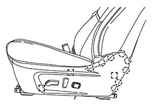
Remove the seat cushion outer finisher (LH). For manual seat:
-
Using a suitable tool, release pawls and remove the lift lever finisher (1).
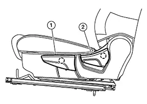
-
Using a suitable tool, release pawl and remove the recline lever (2).
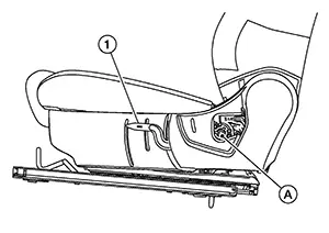
- Remove bolt (A) and lift lever bracket
(1).
-
Using a suitable tool, release pawls and pull to release the metal clips then remove the seat cushion outer finisher (1).

: Metal clip

: Pawl
-
Using a suitable tool, release metal clips from the seat cushion frame.
: Metal clip
-
Using a suitable tool, release pawls and separate.
: Pawl
-
Disconnect the harness connector from the power seat switch.
-
Disconnect the harness connector from the lumbar support switch.
-
Using a suitable tool, release harness retainers and remove cushion outer finisher..
Note:
Take note of harness routing and attachment location for correct installation.
Remove the lower seatback flap trim retainer straps from the seat frame assembly.
Disconnect the harness connector from the cushion heater (if equipped)].
Using a
suitable tool, release cushion heater harness retainers (if
equipped). Note:
Take note of harness routing and attachment location for correct installation.
Using a
suitable tool, release seat belt buckle harness retainers. Note:
Take note of harness routing and attachment location for correct installation.
Release the
seat cushion trim J-clips then remove the seat cushion pad and seat
cushion trim from the seat frame. 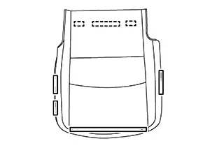 Remove
the seat cushion trim and
seat cushion pad as an assembly from the seat frame
assembly.
Remove
the seat cushion trim and
seat cushion pad as an assembly from the seat frame
assembly.
Separate
the seat cushion trim from the seat cushion pad using the following
steps. Remove the hog rings on the
underside of the seat cushion trim and pad assembly. Remove the hog rings and separate
the seat cushion trim from the seat cushion pad. 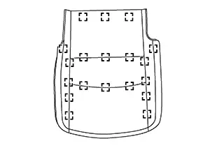
|
|
: Hog Ring |
Remove all pieces of hog rings and discard them.
If
necessary remove the seat cushion outer finisher [RH (1)]. 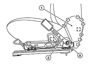 Remove bolt (A). Remove the seat belt buckle (2) and
position aside. Refer to Exploded View. Using
suitable tools, release pawls and metal clips.
Remove bolt (A). Remove the seat belt buckle (2) and
position aside. Refer to Exploded View. Using
suitable tools, release pawls and metal clips.
|
|
: Metal clip |
|
|
: Pawl |
Assembly
Assembly is in the reverse order of disassembly.
CAUTION:
-
Always route side air bag module harness in original location. Replace any deformed or damaged clips with same type and color. Always install clips in the original location in the harness.
-
After work is completed, check that no system malfunction is detected causing the air bag warning lamp to illuminate.
-
If a malfunction is detected by the air bag warning lamp after repair or replacement of the malfunctioning parts, perform the SRS FINAL CHECK. Refer to SRS Final Check.
-
Install new hog rings on the seatback trim in original positions.
-
Use only one hog ring in each designated location.
-
Make sure hog rings are correctly fastened around both the seatback trim and seat frame.
-
Use NISSAN standard hog rings and tools to assemble.
-
Smooth out all wrinkles during assembly.
Other materials:
Squeak and Rattle Trouble Diagnoses
Work Flow
Work Flow
CUSTOMER INTERVIEW
Interview the customer if possible, to determine
the conditions that exist when the noise occurs. Use the Diagnostic
Worksheet during the interview to document the facts and conditions
when the noise occurs and any customer's comments; refer ...
Rear-facing child restraint installation using LATCH
Do not use the LATCH lower anchors if the combined weight of the child and the
child restraint exceeds 65 lbs (29.5 kg). If the combined weight is greater than
65 lbs (29.5 kg), install the child restraint using the vehicle’s seat belt instead
of the lower anchors. Always follow the child re ...
Front Fender
Exploded View
Exploded View
1.
Cowl top side trim cover
2.
Front fender baffle A
3.
...