Nissan Sentra B18 (2020-2025) Service Manual: Drive Belt
Exploded View
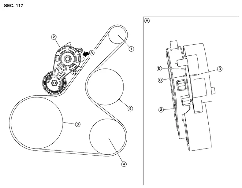
Exploded View
|
1. |
Generator |
2. |
Drive belt auto tensioner |
3. |
Crankshaft pulley |
|
4. |
A/C compressor |
5. |
Water pump |
A. |
View A |
|
B. |
Minimum belt length indicator |
C. |
Maximum belt length indicator |
D. |
Indicator mark |
Removal and Installation
Removal and Installation
REMOVAL
Remove wheel and tire (RH). Refer to Removal and Installation.
Partially remove fender protector. Refer to Exploded View.
Securely hold hexagonal part of the drive belt auto tensioner with a suitable tool and rotate it clockwise.
CAUTION:
Avoid placing hands in a location where pinching may occur if suitable tool accidentally comes off.
Insert a
suitable tool approximately 6 mm (0.24 in) in diameter into the
hole of the retaining boss to secure drive belt auto
tensioner. Note: 
Keep drive belt auto tensioner arm locked after drive belt is removed.
Remove drive belt.
INSTALLATION
Install drive belt onto all pulleys.
CAUTION:
-
Avoid placing hands in location where pinching may occur if suitable tool accidentally comes off.
-
Check that drive belt path is correct.
-
Check the drive belt is securely inside the groove on each pulley.
-
Check for engine oil, engine coolant and other oil or grease on the drive belt and surrounding locations.
Release drive belt auto tensioner and apply tension to drive belt.
Turn crankshaft pulley several times clockwise to equalize tension between each pulley.
Installation of the remaining components is in the reverse order of removal.
Inspection
Inspection
|
1. |
Generator |
2. |
Drive belt auto tensioner |
3. |
Crankshaft pulley |
|
4. |
A/C compressor |
5. |
Water pump |
A. |
View A |
|
B. |
Minimum belt length indicator |
C. |
Maximum belt length indicator |
D. |
Indicator mark |
Warning:
Be sure to perform the these steps when engine is stopped.
Check that
the indicator mark (D) on fixed side of drive belt auto tensioner
is within minimum belt length indicator (B) and maximum belt length
indicator (C) range. Note:
-
Check the drive belt auto tensioners indication when the engine is cold.
-
When new drive belt is installed, the indicator mark on fixed side should be within minimum belt length indicator (B) and maximum belt length indicator (C) range.
Visually check entire drive belt for wear, damage or cracks.
If the indicator mark on the fixed side is out of the possible use range or drive belt are damaged, replace drive belt.
Other materials:
Cooling Fan
Exploded View
Exploded View
1.
Reservoir tank
cap
2.
Reservoir tank
3.
...
P2809-00 Pressure Control Solenoid G
Dtc Description
DTC Description
DTC DETECTION LOGIC
DTC
CONSULT screen terms
(Trouble diagnosis
content)
DTC detection
...
Siri Eyes Free
Apple Siri Eyes Free personal assistant can be accessed directly from the Nissan
Sentra, allowing drivers to use Siri with reduced distraction. Siri Eyes Free operates
in a dedicated voice-only mode, enabling hands-free interaction while keeping your
attention on the road. After pairing a comp ...