Nissan Sentra Service Manual: Differential side oil seal
Exploded View
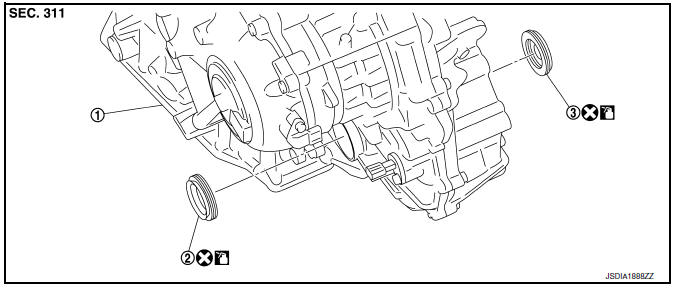
- Transaxle assembly
- Differential side oil seal (left side)
- Differential side oil seal (right side)
 : Vehicle front
 : Always replace after every
disassembly.
 : Genuine NISSAN CVT Fluid NS-3
Removal and Installation
REMOVAL
NOTE:
Cap or plug openings to prevent fluid from spilling.
- Remove the front drive shaft (RH/LH). Refer to FAX-21, "6M/T : Removal and Installation (RH)"(RH), FAX- 18, "6M/T : Removal and Installation (LH)"(LH) and FAX-26, "EXCEPT 6M/T : Removal and Installation" (Except 6M/T).
- Use oil seal remover or a similar means and remove the differential side oil seal.
CAUTION:
When removing the differential side oil seal, be careful not to scratch the oil seal mounting surfaces of the transaxle case and converter housing.
INSTALLATION
Installation is in the reverse order of removal.
CAUTION:
- Do not reuse differential side oil seal.
- Apply Genuine NISSAN CVT Fluid NS-3 to the differential side oil seal lip and around the oil seal.
- When inserting the drive shaft, be sure to use a protector
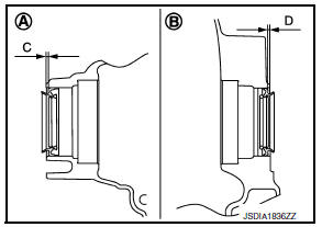
Using Tool, drive the differential side oil seal in until the amount of oil seal projection from the case edge matches dimensions (C) and (D).
Tool number : KV38107900
CAUTION:
Be careful not to scratch the lip of the differential side oil seal when press-fitting it.
(A) : Differential side oil seal (LH)
(B) : Differential side oil seal (RH)
Dimension “C” :Height difference from case end surface is within 1.8 ± 0.5 mm (0.071 ± 0.020 in).
Dimension “D” :Height difference from case end surface is within 1.8 ± 0.5 mm (0.071 ± 0.020 in).
NOTE:
The reference is the pull-in direction of the differential side oil seal.
Drift to be used:
| Location | Commercial Service Tools |
| Transaxle case side | Commercial service tool with outer dia. 56 mm (2.20 in) and inner dia. 50 mm (1.97 in) |
| Converter housing side |
Inspection and Adjustment
INSPECTION AFTER INSTALLATION
Drive the vehicle and check visually that there is no leakage of CVT fluid.
ADJUSTMENT AFTER INSTALLATION
Adjust CVT fluid level. Refer to TM-251, "Adjustment".
 Output speed sensor
Exploded View
Transaxle assembly
Output speed sensor
O-ring
: Vehicle front
: Always replace after every
disassembly.
: NВ·m (kg-m, in-lb)
: Genuine NISSAN CVT Fluid NS-3
R ...
 Water hose
Exploded View
Water outlet
Heater thermostat assembly
Hose clamp
CVT oil warmer
Water hose
To thermostat housing
To engine oil cooler
: Always replace after every
disass ...
Other materials:
Daytime light system inoperative
Description
The daytime light system is inoperative even though the combination switch
(lighting and turn signal switch)
and parking brake switch are in the normal setting, also whenever engine is
operating.
Diagnosis procedure
1.Check daytime light operation
Perform bcm(headlamp) daytim ...
Charging system
System Diagram
System Description
The generator provides DC voltage to operate the vehicle's electrical system
and to keep the battery charged.
The voltage output is controlled by the IC regulator.
Component Description
...
P0196 EOT Sensor
DTC Logic
DTC DETECTION LOGIC
NOTE:
If DTC P0196 is displayed with DTC P0197 or P0198, first perform the
trouble diagnosis for DTC P0197 or
P0198. Refer to EC-264, "DTC Logic".
DTC No.
CONSULT screen terms
(Trouble diagnosis content)
DTC detecting condition
Possib ...
