Nissan Sentra Service Manual: Cooling fan control
SYSTEM DIAGRAM
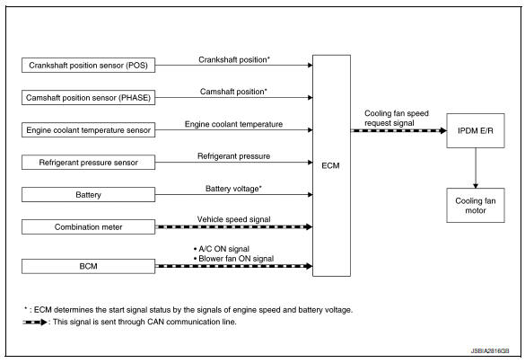
SYSTEM DESCRIPTION
ECM controls cooling fan speed corresponding to vehicle speed, engine coolant temperature, refrigerant pressure, air conditioner ON signal. Then control system has 3-step control [HIGH/LOW/OFF].
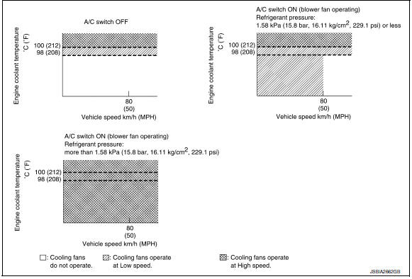
Cooling Fan Operation
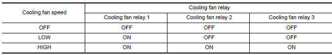
Cooling Fan Relay Operation
When IPDM E/R recieves a cooling fan speed request signal, IPDM E/R controls the cooling fan ralay 1, 2 and 3.
 Air conditioning cut control
AIR CONDITIONING CUT CONTROL : System Description
SYSTEM DIAGRAM
INPUT/OUTPUT SIGNAL CHART
Sensor
Input Signal to ECM
ECM function
Actuator
Crankshaft position sensor ( ...
 Starter motor drive control
STARTER MOTOR DRIVE CONTROL : System Description
SYSTEN DIAGRAM
*1: CVT models
*2: M/T models
INPUT/OUTPUT SIGNAL CHART
Sensor
Input signal to ECM
ECM function
Actuator
...
Other materials:
P0603 ECM
DTC Logic
DTC DETECTION LOGIC
DTC No.
CONSULT screen terms
(Trouble diagnosis content)
DTC detecting condition
Possible cause
P0603
ECM BACK UP CIRCUIT
[Internal control module keep
alive memory (KAM) error]
Malfunction in the internal back up RAM o ...
Steering wheel turning force is heavy or light
Description
Steering wheel turning force is heavy or light.
Diagnosis Procedure
1.PERFORM SELF-DIAGNOSIS
With CONSULT
Turn the ignition switch OFF to ON.
Perform EPS self-diagnosis.
Is any DTC detected?
YES >> Check the DTC. Refer to STC-14, "DTC Index".
NO & ...
C1704, C1705, C1706, C1707 Low tire pressure
DTC Logic
NOTE:
The Signal Tech II Tool (J-50190) can be used to perform the following
functions. Refer to the Signal Tech II
User Guide for additional information.
Activate and display TPMS transmitter IDs
Display tire pressure reported by the TPMS transmitter
Read TPMS DTCs
Register ...
