Nissan Sentra Service Manual: Cooler pipe and hose
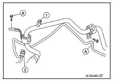
Exploded view
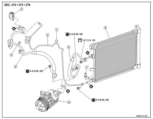
- High-pressure service port
- High-pressure pipe
- Expansion valve
- Low-pressure service port
- Low-pressure flexible hose
- Compressor
- Refrigerant pressure sensor
- Condenser and liquid tank assembly
- High-pressure flexible hose
Low-pressure flexible hose
Low-pressure flexible hose : removal and installation
REMOVAL
- Discharge the refrigerant. Refer to HA-23, "Recycle Refrigerant".
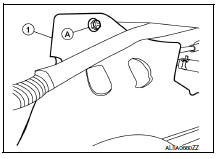
- Remove the upper torque rod bolts (A) and the upper torque rod (1).
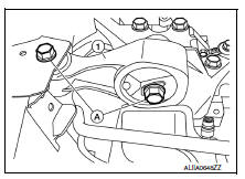
- Remove the washer tank inlet bolt (A), then pull the washer tank inlet (1) up and out of the washer tank.
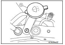
- Remove the engine ground bolts (A) and the engine ground (1).
- Remove the A/C pipe bracket bolts (A).
(1): Low-pressure service port
(2): High-pressure service port
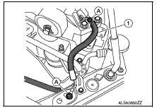
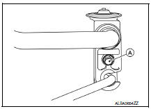
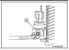
- Remove the push nut (A) from the expansion valve insulator (1) and reposition.
- Remove the bolt (A) that retains the high-pressure pipe and lowpressure flexible hose to the expansion valve, then disconnect the low-pressure flexible hose from the expansion valve and high-pressure pipe.
CAUTION:
Cap or wrap the joint of the hose with suitable material such as vinyl tape to avoid the entry of air.
- Remove the front under cover. Refer to EXT-31, "ENGINE UNDER COVER : Removal and Installation".
- Remove the bolt that retains the high-pressure flexible hose to the compressor, then disconnect the highpressure flexible hose from the compressor.
- Remove the bolt that retains the low-pressure flexible hose to the compressor, then disconnect the lowpressure flexible hose from the compressor.
- Remove the low-pressure flexible hose.
INSTALLATION
Installation is in the reverse order of removal.
CAUTION:
- Do not reuse O-rings.
- Apply A/C oil to the new O-rings.
- After charging refrigerant, check for leaks. Refer to HA-21, "Leak Test".
High-pressure flexible hose
High-pressure flexible hose : removal and installation
REMOVAL
- Discharge the refrigerant. Refer to HA-23, "Recycle Refrigerant".
- Remove the core support upper cover. Refer to HA-39, "Exploded View".
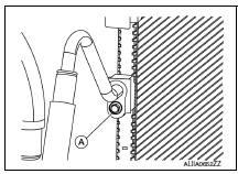
- Remove the bolt (A) that retains the high-pressure flexible hose to the condenser, then disconnect the high-pressure flexible hose from the condenser and liquid tank assembly.
CAUTION:
Cap or wrap the joint of the hose with suitable material such as vinyl tape to avoid the entry of air.
- Remove the bolt that retains the high-pressure flexible hose to the compressor, then disconnect the highpressure flexible hose from the compressor.
- Remove the high-pressure flexible hose.
INSTALLATION
Installation is in the reverse order of removal.
CAUTION:
- Do not reuse O-rings.
- Apply A/C oil to new O-rings.
- After charging refrigerant, check for leaks. Refer to HA-21, "Leak Test".
High-pressure pipe
High-pressure pipe : removal and installation
REMOVAL
- Discharge the refrigerant. Refer to HA-23, "Recycle Refrigerant".
- Remove the core support upper. Refer to HA-39, "Exploded View".
- Remove the low-pressure flexible hose. Refer to HA-35, "LOW-PRESSURE FLEXIBLE HOSE : Removal and Installation".
- Remove the bolt (A) that retains the high-pressure pipe to the condenser, then disconnect the high-pressure pipe from the condenser and liquid tank assembly.
CAUTION:
Cap or wrap the joint of the pipe with a suitable material such as vinyl tap to avoid the entry of air.
- Remove the high-pressure pipe.
INSTALLATION
Installation is in the reverse order of removal.
CAUTION:
- Do not reuse O-rings.
- Apply A/C oil to new O-rings.
- After charging refrigerant, check for leaks. Refer to HA-21, "Leak Test".
 Compressor
Exploded view
With air conditioning
Compressor
Front
Without air conditioning
A/c idler pulley
A/c idler pulley bracket
Compressor
Compressor : removal and installation
REM ...
 Condenser
Exploded view
Core support upper cover
High-pressure pipe
High-pressure flexible hose
Refrigerant pressure sensor
Condenser and liquid tank assembly
Core support upper
Front
Conde ...
Other materials:
System
Body control system
Body control system : system description
OUTLINE
BCM (Body Control Module) controls the various electrical components. It
inputs the information required to
the control from CAN communication and the signal received from each switch
and sensor.
BCM has combination ...
Bluetooth® Hands-Free Phone System without
Navigation System (Type B) (if so equipped)
WARNING
Use a phone after stopping your vehicle
in a safe location. If you have to use a
phone while driving, exercise extreme
caution at all times so full attention may
be given to vehicle operation.
If you are unable to devote full attention
to vehicle operation ...
Types of tires
WARNING
When changing or replacing tires, be
sure all four tires are of the same type
(i.e., Summer, All Season or Snow) and
construction. A NISSAN dealer may be
able to help you with information about
tire type, size, speed rating and
availability.
Replacement ...
