Nissan Sentra B18 (2020-2025) Service Manual: Component Parts
Telematics System
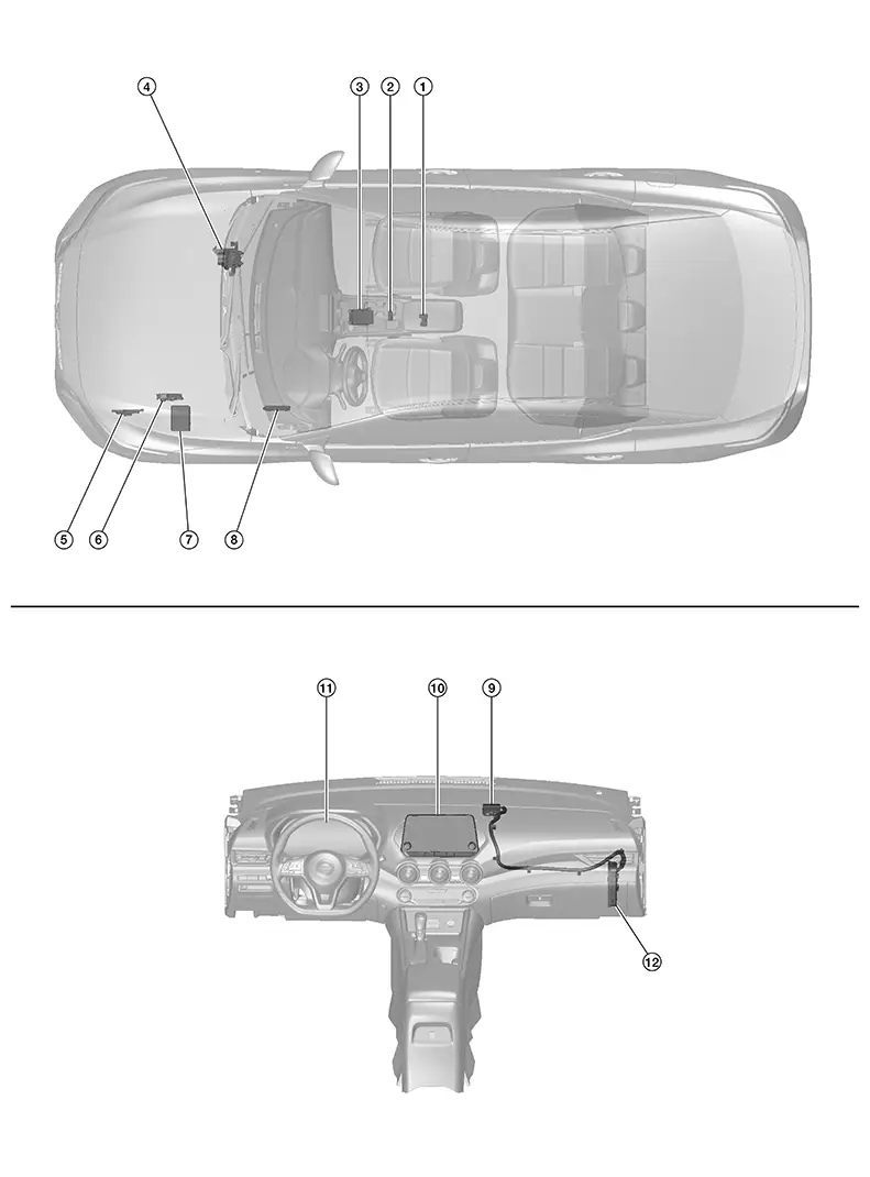
Component Parts Location
|
No. |
Component |
Function |
|---|---|---|
|
1. |
Air bag diagnosis sensor unit |
Provides TCU with air bag crash order signal via CAN communication. Refer to Component Parts Location for detailed component location. |
|
2. |
Moonroof switch assembly (telematics switch) |
Refer to Moonroof Switch Assembly (Telematics Switch). |
|
3. |
ABS (Anti-lock Braking System) actuator and electric unit (control unit) |
Provides TCU with ABS malfunction signal via CAN communication. Refer to Component Parts Location for detailed component location. |
|
4. |
TCM (Transmission Control Module) (with CVT models) |
Provides TCU with transmission range indication signal via CAN communication. Refer to Component Parts Location for detailed component location. |
|
5. |
ECM (Engine Control Module) |
Provides TCU with the following signals via CAN communication:
Refer to Component Parts Location for detailed component location. |
|
6. |
IPDM E/R (Intelligent Power Distribution Module Engine Room) |
Provides TCU with anti-theft horn status signal via CAN communication. Refer to Component Parts Location for detailed component location. |
|
7. |
BCM (Body Control Module) |
Provides TCU with door switches state signal via CAN communication. Refer to Component Parts Location for detailed component location. |
|
8. |
Microphone |
Refer to Microphone. |
|
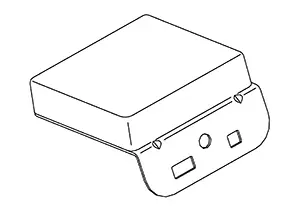
9. |
Telematics antenna |
Refer to Telematics Antenna. |
|
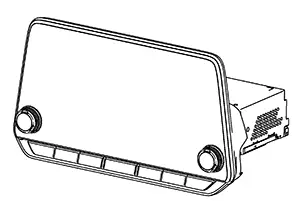
10. |
AV control unit |
Refer to AV Control Unit. |
|
11. |
Combination meter |
Provides TCU with the following signals via CAN communication:
Refer to Component Parts Location for detailed component location. |
|
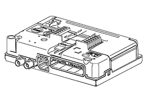
12. |
TCU (Telematics Communication Unit) |
Refer to TCU. |
Av Control Unit
-
A 8-inch color display with multi-touch control, an AM/FM/HD electronic tuner radio with RDS and camera controller are integrated into the AV Control unit.
-
The 8-inch color display is a high resolution monitor that includes touch panel functions.
Tcu
-
Telematics Communication Unit (TCU) is installed in RH side of instrument panel behind the glove box.
-
A radio communication terminal and SIM card are built into the unit and data is sent and received in SMS*, DTMF tone signal with the NissanConnect® center through the TEL antenna.
Note:
*: SMS stands for Short Message Service. It is also referred to as Text Messaging, Short Mail, etc. is the service that performs text based message communication.
-
It is connected to the AV control unit with the USB harness for sound signal input/output and USB communication.
-
It is connected to the air bag diagnosis sensor unit via CAN communication. TCU performs an emergency report when the air bag is inflated.
-
VIN information necessary for the Telematics service is memorized.
-
Audio signals received during SOS/Operator call are transmitted from TCU to each speaker via the AV control unit.
-
During the communication with NissanConnect center, TCU transmits a TEL ON signal to the AV control unit to prohibit the use of Bluetooth® hands-free phone.
Telematics Antenna
-
The telematics antenna consists of TEL antenna and GPS antenna.
-
It is installed in the instrument panel.
 Note:
Note:
The placement of an object on the instrument panel may cause desensitization in the receiver sensitivity.
Telematics Switch
-
The moonroof switch assembly (telematics switch) is located on the map lamp assembly.
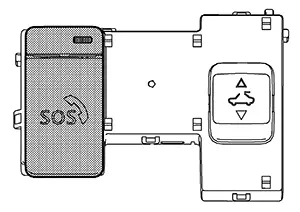
-
The moonroof switch assembly (telematics switch) is connected to TCU and transmits an operation signal.
-
The state of LED (ON/Blink/OFF) shows the status of SOS call.
LED ON
:SOS Call available
LED Blink
:SOS Call in communication
LED OFF
:Out of service area or system error
Microphone
-
Microphone is installed on the map lamp assembly.
-
The microphone is used for the operation of the NissanConnect, hands-free phone system, voice recognition function.
-
The power is supplied from the TCU to the microphone, transmitting sound signals to the TCU during operation of the NissanConnect system, hands-free phone communication, and voice recognition.

 System
System Description
System Description
SYSTEM DIAGRAM
Display Audio System - Without Bose Audio System With 8” Color
Display Display Audio System - With Bose Audio System With 8”
Color
...
Other materials:
Front wiper motor lo circuit
Component function check
1. Check front wiper lo operation
Ipdm e/r auto active test
Start ipdm e/r auto active test. Refer to pcs-9, "diagnosis description"
(with intelligent key system) or
pcs-37, "diagnosis description" (without intelligent key system).
Check tha ...
Brake Fluid Level and Leaks
Inspection
Inspection
BRAKE FLUID LEVEL
Make sure that the brake fluid level in the
master cylinder reservoir tank is between the MAX and MIN
lines.
Visually check around the master cylinder
reservoir tank for brake fluid leaks.
...
Ambient sensor signal circuit
Description
It detects outside air temperature and converts it into a resistance value
which is then input into the combination
meter.
Diagnosis Procedure
Regarding wiring diagram information, refer to mwi-28, "wiring diagram".
1.Check ambient sensor signal circuit
Turn igniti ...
