Nissan Sentra Service Manual: Ambient sensor signal circuit
Description
It detects outside air temperature and converts it into a resistance value which is then input into the combination meter.
Diagnosis Procedure
Regarding wiring diagram information, refer to mwi-28, "wiring diagram".
1.Check ambient sensor signal circuit
- Turn ignition switch off.
- Disconnect combination meter connector and ambient sensor connector.
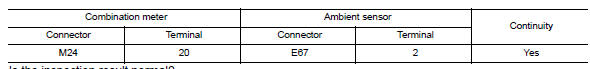
- Check continuity between combination meter harness connector and ambient sensor harness connector.

- Check continuity between combination meter harness connector and ground.
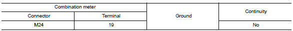
Is the inspection result normal? Yes >> go to 2.
No >> repair or replace harness or connector.
2.Check ambient sensor signal ground circuit
Check continuity between combination meter harness connector and ambient sensor harness connector.
Is the inspection result normal? YES >> Inspection End.
NO >> Repair or replace harness or connector.
Component Inspection
1.Check ambient sensor
- Turn ignition switch OFF.
- Disconnect ambient sensor connector.
- Check resistance between ambient sensor terminals.
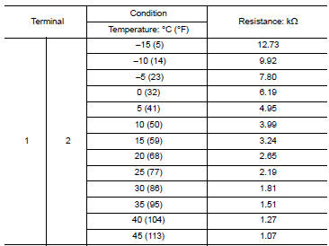
Is the inspection result normal? Yes >> inspection end.
No >> replace ambient sensor. Refer to hac-106, "removal and installation".
 Parking brake switch signal circuit
Component function check
1.Check parking brake switch operation
Check that brake warning lamp in combination meter turns on/off when parking
brake is actuated.
Is the inspection result normal?
...
 A/c auto amp. Connection recognition signal circuit
Description
A/c auto amp. Transmits the a/c auto amp. Connection recognition signal to
the combination meter
Diagnosis procedure (with manual a/c)
Regarding wiring diagram information, refer to ...
Other materials:
Precaution
Precaution for supplemental restraint system (srs) "air bag" and "seat belt pre-tensioner"
The Supplemental Restraint System such as “AIR BAG” and “SEAT BELT PRE-TENSIONER”,
used along
with a front seat belt, helps to reduce the risk or severity of injury ...
System description
DESCRIPTION
Engine Cooling System Schematic
CVT Models
Radiator
Water inlet
Reservoir tank
Thermostat
Engine oil cooler
Thermostat housing
Water pump
Cylinder head
Cylinder block
Water control valve
Water outlet
Heater
Electric throttle control actuator
CVT oil wa ...
How to select piston and bearing
Description
Selection points
Selection parts
Selection items
Selection methods
Between cylinder block and
crankshaft
Main bearing
Main bearing grade (bearing
thickness)
Determined by match of cylinder
block bearing housing
grade (inner diameter of hous ...
