Nissan Sentra B18 (2020-2025) Service Manual: Component Parts
Automatic Emergency Braking System
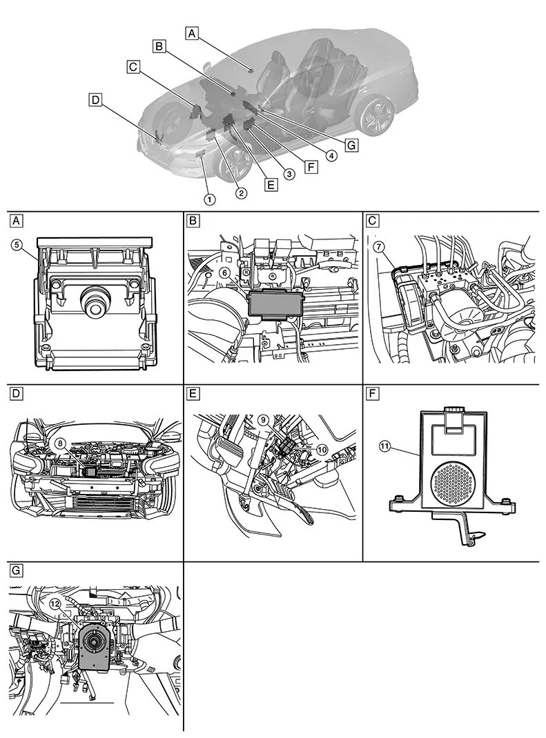
Component Parts Location
Component Parts Location
|
A. |
Center of windshield (view with component removed from Nissan Sentra vehicle) |
B. |
Right side of instrument panel (view with glove box assembly removed) |
C. |
Right side of engine compartment |
|
D. |
Center of radiator area (view with front bumper cover removed) |
E. |
Brake pedal area |
F. |
Left side of instrument panel (view with component removed from Nissan Sentra vehicle) |
|
G. |
Steering wheel area |
||||
|
No. |
Component |
Function |
|
|---|---|---|---|
|
1. |
TCM (Transmission Control Module) |
Mainly transmits the following signals to ABS actuator and electric unit (control unit) via CAN communication:
|
|
|
2. |
ECM (Engine Control Module) |
Mainly transmits the following signals to ABS actuator and electric unit (control unit) via CAN communication:
Mainly receives the following signal from ABS actuator and electric unit (control unit) via CAN communication:
|
|
|
3. |
BCM (Body Control Module) |
Mainly receives the following signal from ABS actuator and electric unit (control unit) via CAN communication:
|
|
|
4. |
Combination meter |
Refer to Combination Meter (Type A) or Combination Meter (Type B) for detailed component location. |
|
|
5. |
Front camera unit |
Refer toFront Camera Unit for detailed component location. |
|
|
6. |
ADAS (Advanced Driver Assistant System) control unit |
Refer to ADAS Control Unit for detailed component location. |
|
|
7. |
ABS (Anti-lock Braking System) actuator and electric unit (control unit) |
Pump/motor |
Refer to ABS Actuator and Electric Unit (Control Unit). |
|
Motor relay |
|||
|
Actuator relay (main relay) |
|||
|
ABS IN valve |
|||
|
ABS OUT valve |
|||
|
Cut valve 1 |
|||
|
Cut valve 2 |
|||
|
Pressure sensor |
|||
|
8. |
Distance sensor |
Refer to Distance Sensor for detailed component location. |
|
|
9. |
Brake pedal position switch |
Detects the operation status of brake pedal and transmits converted electric signal to ABS actuator and electric unit (control unit). |
|
|
10. |
Stop lamp switch |
Refer to Stop Lamp Switch. |
|
|
11. |
Driver assistance buzzer |
Refer to Driver Assistance Buzzer for detailed component location. |
|
|
12. |
Chassis control module (with built in steering angle sensor) |
Refer to Chassis Control Module (with built in steering angle sensor) for detailed component location. |
|
Other materials:
Refrigerant
Description
Description
CONNECTION OF SERVICE TOOLS AND
EQUIPMENT
1.
Shut-off valve
2.
A/C service valve
...
Driver Side
Exploded View
Exploded View
POWER SEAT
1.
Seatback trim
2.
Seatback pad
3.
...
Low Tire Pressure Warning Lamp Does Not Turn Off
Symptom Description
Symptom Description
The low tire pressure warning lamp does not turn
OFF after several seconds is passed after the engine starts.
Diagnosis Procedure
Diagnosis Procedure
CHECK TIRE PRESSURE
Ignition switch ...