Nissan Sentra B18 (2020-2025) Service Manual: System
System Description
System Description
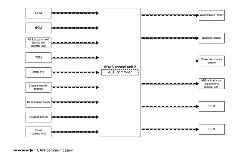
SYSTEM DIAGRAM
|
Component |
Description |
|---|---|
|
ECM |
Component Description |
|
BCM |
System Description |
|
ABS actuator and electric unit (control unit) |
ABS Actuator and Electric Unit (Control Unit) |
|
IPDM E/R *1 |
System Description |
|
TCM *2 |
TCM |
|
Chassis control module |
Chassis Control Module (With Built In Steering Angle Sensor) |
|
Distance sensor |
Distance Sensor |
|
Front camera unit |
Front Camera Unit |
|
Combination meter |
Combination Meter(4.2 inch Information Display) or Combination Meter(7 inch Information Display) |
|
ADAS control unit 2 |
ADAS Control Unit 2 |
|
Driver assistance buzzer |
Driver Assistance Buzzer |
*1: M/T models
*2: CVT models
ADAS CONTROL UNIT 2 INPUT/OUTPUT SIGNAL ITEM
Input Signal Item
|
Transmit unit |
Signal name |
Description |
||
|---|---|---|---|---|
|
ECM |
CAN communication |
Closed throttle position signal |
Receives idle position state (ON/OFF) |
|
|
Accelerator pedal position signal |
Receives accelerator pedal position (angle) |
|||
|
Engine speed signal |
Receives engine speed |
|||
|
BCM |
CAN communication |
Stop lamp switch signal |
Receives an operational state of the brake pedal |
|
|
Brake pedal position switch signal |
Receives an operational state of the brake pedal |
|||
|
ABS actuator and electric unit (control unit) |
CAN communication |
ABS malfunction signal |
Receives a malfunction state of ABS |
|
|
ABS operation signal |
Receives an operational state of ABS |
|||
|
ABS warning lamp signal |
Receives an ON/OFF state of ABS warning lamp |
|||
|
TCS malfunction signal |
Receives a malfunction state of TCS |
|||
|
TCS operation signal |
Receives an operational state of TCS |
|||
|
VDC OFF signal |
Receives an ON/OFF state of VDC |
|||
|
VDC malfunction signal |
Receives a malfunction state of VDC |
|||
|
VDC operation signal |
Receives an operational state of VDC |
|||
|
Nissan Sentra Vehicle speed signal (ABS) |
Receives wheel speeds of four wheels |
|||
|
Yaw rate signal |
Receives yaw rate acting on the Nissan Sentra vehicle |
|||
|
Side G sensor signal |
Receives lateral G acting on the Nissan Sentra vehicle |
|||
|
IPDM E/R *1 |
CAN communication |
Neutral position signal |
Receives a neutral position |
|
|
Reverse position signal |
Receives a reverse position |
|||
|
TCM *2 |
CAN communication |
Input speed signal |
Receives the number of revolutions of input shaft |
|
|
Current gear position signal |
Receives a current gear position |
|||
|
Shift position signal |
Receives a selector lever position |
|||
|
Output shaft revolution signal |
Receives the number of revolutions of output shaft |
|||
|
Chassis control module |
CAN communication |
Steering angle sensor malfunction signal |
Receives a malfunction state of steering angle sensor |
|
|
Steering angle sensor signal |
Receives the number of revolutions, turning direction of the steering wheel |
|||
|
Steering angle speed signal |
Receives the turning angle speed of the steering wheel |
|||
|
Combination meter |
CAN communication |
System selection signal |
Receives a selection state of each item selected with the information display |
|
|
Distance sensor |
CAN communication |
Distance sensor signal |
Receives detection results, such as the presence or absence of a leading Nissan Sentra vehicle and distance from the vehicle |
|
|
Front camera unit |
CAN communication |
Pedestrian ahead signal |
Receives detection results of pedestrian ahead of Nissan Sentra vehicle |
|
|
Nissan Sentra Vehicle ahead signal |
Receives detection results of Nissan Sentra vehicle ahead |
|||
*1: M/T models
*2: CVT models
Output Signal Item
|
Reception unit |
Signal name |
Description |
||
|---|---|---|---|---|
|
Combination meter |
CAN communication |
Meter display signal |
Transmits a signal to display a state of the system on the information display |
|
|
AEB warning lamp signal |
Transmits a signal to turn ON the lamp |
|||
|
Distance sensor |
CAN communication |
Nissan Sentra Vehicle speed signal |
Transmits a Nissan Sentra vehicle speed calculated by the ADAS control unit 2 |
|
|
Steering angle sensor signal |
Transmits a steering angle sensor signal received from the steering angle sensor |
|||
|
ABS actuator and electric unit (control unit) |
CAN communication |
Brake fluid pressure control signal |
Transmits a brake fluid pressure control signal to activates the brake |
|
|
BCM |
CAN communication |
Stop lamp request signal |
Transmits a signal to activates the stop lamp |
|
|
ECM |
CAN communication |
Torque request signal |
Transmits a signal to control the engine torque |
|
|
Driver assistance buzzer signal |
Driver assistance buzzer signal |
Transmits a driver assistance buzzer signal to turn ON the buzzer | ||
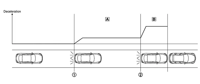
FUNCTION DESCRIPTION
-
The AEB system measures the distance from a Nissan Sentra vehicle ahead using the distance sensor installed in the front grill and front camera unit installed in the windshield glass.
-
The AEB system detects a pedestrian using the front camera unit installed in the windshield glass.
-
When the system judges that a Nissan Sentra vehicle or pedestrian is being approached, warning indicators are displayed on the information display and at the same time a warning chime sounds, and the brake is operated.
-
When it is further judged that the Nissan Sentra vehicle or pedestrian may collide with the vehicle ahead, the system operates the brake strongly to avoid collision while warning indicators are displayed on the information display and at the same time a warning chime sounds.
|
|
Start of warning and partial brake |
|
Start of harder brake |
||
|
|
Applies partial braking |
|
Harder brake |


|
Situation |
Brake |
Warning |
|
|---|---|---|---|
|
No obstacle approached |
No operation |
— |
|
|
|
Start of warning and partial brake |
Partial brake 
|
|
|
|
Start of harder brake |
Harder brake
|
|
CAUTION:
It is the driver′s responsibility to stay alert, drive safely and be in control of the Nissan Sentra vehicle at all times. As there is a performance limit, it may not provide a warning or brake in certain conditions.
OPERATION DESCRIPTION
-
The distance sensor measures the distance from the Nissan Sentra vehicle ahead and transmits the distance sensor signal to the ADAS control unit 2.
-
The front camera unit measures the distance from a pedestrian and transmits the pedestrian ahead signal to ADAS control unit 2.
-
The ADAS control unit 2 judges the possibility of a collision from the distance sensor signal, the pedestrian ahead signal and the Nissan Sentra vehicle speed.
-
The ADAS control unit 2 performs the following operations according to the degree of possibility of a collision.
-
Transmits the driver assistance buzzer signal to the driver assistance buzzer and sounds the buzzer.
-
Transmits the meter display signal to the combination meter and displays a state of the system on the information display.
-
Transmits the brake fluid pressure control signal to the ABS actuator and electric unit (control unit) via chassis control module and performs the brake control
-
Transmits the stop lamp request signal to the BCM and turns ON the stop lamp.
-

-
ON/OFF of AEB system is performed with the information display.
-
When the ignition switch is turned from OFF to ON, the system is automatically activated even if it is OFF.
-
The AEB system operates under the following conditions.
-
The AEB system will function when the Nissan Sentra vehicle is driven at speeds of approximately 5 km/h (3 MPH) and above, and when the vehicle′s speed is approximately 5 km/h (3 MPH) faster than that of the Nissan Sentra vehicle ahead. (For vehicle)
-
Operation Condition
ADAS control unit 2 performs the control when the following conditions are satisfied.
-
When the AEB system setting on the information display is ON.
-
When the Nissan Sentra vehicle speed is above approximately 5 km/h (3 MPH). (For vehicle)
-
When the vehicle speed is within the range of approximately 10 – 60 km/h (5 – 37 MPH). (For pedestrian)
-
There is a possibility of a collision with the Nissan Sentra vehicle and pedestrian ahead.
No Operation Condition
The ADAS control unit 2 is not operate when the system is under the conditions of the no operation condition.
-
When the AEB system setting on the information display is OFF.
-
When the Nissan Sentra vehicle and pedestrian ahead is not detected.
-
When the vehicle speed is below approximately 10 km/h (5 MPH). (For pedestrian)
Operation Cancellation Condition
The ADAS control unit 2 cancels the operation when the system is under any conditions of the operation cancellation condition.
-
When the system judges that the Nissan Sentra vehicle comes to a standstill by the system control.
-
When the system malfunction occurs.
-
When the distance sensor area of the front grill is dirty and the measurement of the distance between the Nissan Sentra vehicles becomes difficult. (For vehicle)
-
When the view of ahead is hard is recognized due to dirt around front camera unit of windshield. (For pedestrian)
Fail-Safe
Fail-safe
ADAS Control unit 2
Refer to Fail-safe (ADAS Control Unit 2).
Distance Sensor
If a malfunction occurs in the distance sensor, ADAS control unit 2 cancels control, sounds a beep, and turns ON the warning indicator on the information display.
Front Camera Unit
FAIL-SAFE CONTROL BY DTC
If a malfunction occurs in front camera unit, ADAS control unit 2 cancels control, of AEB/ LDW/ ICC/ TSR systems.
At this time turns ON the AEB warning lamp and indicates the warning message on information display.
TEMPORARY DISABLED STATUS AT HIGH TEMPERATURE
-
If the Nissan Sentra vehicle is parked in direct sunlight under high temperature conditions, the system may be deactivated automatically. At this time, ADAS control unit 2 turns ON the AEB warning lamp and indicates the warning message on the information display.
-
When the interior temperature is reduced, the system will resume operation automatically.
-
When Nissan Sentra vehicle front identification is difficult due to soiling of windshield glass and strong light shining from the front, operation may be canceled temporarily. At this time, ADAS control unit 2 turns ON the AEB warning lamp.
Warning Lamp/indicator Lamp
Warning Lamp/Indicator Lamp
|
Name |
Design |
Function |
|---|---|---|
|
AEB warning lamp |
|
|

Other materials:
Parking Brake System. Foot Pedal
Precaution. Precautions
Precautions
Precaution for Supplemental Restraint System (srs) "air Bag" and "seat Belt Pre-Tensioner"
Precaution for Supplemental Restraint System (SRS) "AIR BAG" and "SEAT BELT PRE-TENSIONER"
The Supplemental Restraint System such as
“AIR BAG” and “SEAT BEL ...
U1040 Eng Comm Circuit
Dtc Description
DTC Description
DTC DETECTION LOGIC
DTC
CONSULT screen terms
(Trouble diagnosis
content)
DTC detection
condition
...
P062f Ecm
Dtc Description
DTC Description
DTC DETECTION LOGIC
DTC
CONSULT screen terms
(Trouble diagnosis
content)
DTC detection
conditi ...