Nissan Sentra Service Manual: Clutch pedal
Inspection and Adjustment
INSPECTION
The Height of Clutch Pedal
- Pull back the floor trim and remove front floor spacer (LH) for access to floor panel.
- Check that the clutch pedal height (H1) from the floor panel (1) is within the reference value.
Clutch pedal height (H1)
- Replace clutch pedal if the height is outside the reference value.
Position of Clutch Interlock Switch (if equipped)
Check that the clearance (C) between the thread end of clutch interlock switch (1) and stopper rubber (2) is within the specification range while clutch pedal is fully depressed.
Clearance (C) : Refer to CL-20, "Clutch Pedal".
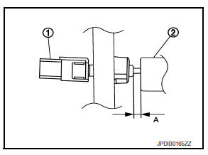
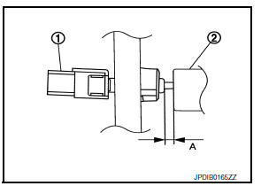
Position of Clutch Pedal Position Switch (if equipped) Check that the clearance (A) between the thread end of clutch pedal position switch (1) and clutch pedal (2) is within the specification range while clutch pedal is fully released.
Clearance (A) : Refer to CL-20, "Clutch Pedal".
ADJUSTMENT
Position of Clutch Interlock Switch (if equipped)
- Disconnect the harness connector from the clutch interlock switch.
- Rotate the clutch interlock switch (1) 45 degrees counterclockwise to release from bracket.
- With the clutch pedal fully depressed, insert the clutch interlock switch (1) until it contacts the stopper rubber (2).
- Rotate the clutch interlock switch 45 degrees clockwise to set clearance (A) between the clutch interlock switch (1) and stopper rubber (2).
CAUTION:
The clearance (C) must be within the specification range.
Clearance (C) : Refer to CL-20, "Clutch Pedal".
NOTE:
Fully depressed clutch pedal means a clutch pedal condition that the clutch pedal lever contacts the pedal stopper rubber.
Position of Clutch Pedal Position Switch (if equipped)
- Disconnect the harness connector from the clutch pedal position switch.
- Rotate the clutch pedal position switch 45 degrees counterclockwise to release from bracket.
- Insert the clutch pedal position switch (1) until it contacts the clutch pedal (2).
- Rotate the clutch pedal position switch 45 degrees clockwise to set clearance (A) between the clutch pedal position switch (1) and clutch pedal (2).
Clearance (A) : Refer to CL-20, "Clutch Pedal".

 Clutch fluid
Inspection
FLUID LEAKAGE
Check clutch line for cracks, deterioration or other damage. Replace any
damaged parts.
Check for fluid leakage by fully depressing clutch pedal while engine is
r ...
Other materials:
M&A branch line circuit
Diagnosis procedure
1.Check connector
Turn the ignition switch off.
Disconnect the battery cable from the negative terminal.
Check the terminals and connectors of the combination meter for damage,
bend and loose connection
(unit side and connector side).
Is the inspection result nor ...
Headlamp (hi) circuit
Description
The IPDM E/R (intelligent power distribution module engine room) controls the
headlamp high relay based on
inputs from the BCM over the CAN communication lines. When the headlamp high
relay is energized, power
flows through fuses 41 and 42, located in the IPDM E/R. Power then flo ...
P0340 CMP Sensor (PHASE)
DTC Logic
DTC DETECTION LOGIC
DTC No.
CONSULT screen terms
(Trouble diagnosis content)
DTC detecting condition
Possible cause
P0340
CMP SEN/CIRC-B1
(Camshaft position sensor
“A” circuit bank 1)
The cylinder No. signal is not sent to ECM fo ...
