Nissan Sentra Service Manual: P0340 CMP Sensor (PHASE)
DTC Logic
DTC DETECTION LOGIC
| DTC No. | CONSULT screen terms (Trouble diagnosis content) | DTC detecting condition | Possible cause |
| P0340 | CMP SEN/CIRC-B1 (Camshaft position sensor “A” circuit bank 1) |
|
|
DTC CONFIRMATION PROCEDURE
1.PRECONDITIONING
If DTC Confirmation Procedure has been previously conducted, always perform the following procedure before conducting the next test.
- Turn ignition switch OFF and wait at least 10 seconds.
- Turn ignition switch ON.
- Turn ignition switch OFF and wait at least 10 seconds.
TESTING CONDITION:
Before performing the following procedure, confirm that battery voltage is more than 10.5 V with ignition switch ON.
>> GO TO 2.
2.PERFORM DTC CONFIRMATION PROCEDURE-1
- Start engine and let it idle for at least 5 seconds.
If engine does not start, crank engine for at least 2 seconds.
- Check 1st trip DTC.
Is 1st trip DTC detected? YES >> Proceed to EC-280, "Diagnosis Procedure".
NO >> GO TO 3.
3.PERFORM DTC CONFIRMATION PROCEDURE-2
- Maintaining engine speed at more than 800 rpm for at least 5 seconds.
- Check 1st trip DTC.
Is 1st trip DTC detected? YES >> Proceed to EC-280, "Diagnosis Procedure".
NO >> INSPECTION END
Diagnosis Procedure
1.CHECK STARTING SYSTEM
Turn ignition switch to START position.
Does the engine turn over? Does the starter motor operate? YES >> GO TO 2.
NO >> Check starting system. Refer to STR-20, "Work Flow (With GR8-1200 NI)" or STR-24, "Work Flow (Without GR8-1200 NI)".
2.CHECK CAMSHAFT POSITION (CMP) SENSOR (PHASE) POWER SUPPLY
- Turn ignition switch OFF
- Disconnect camshaft position (CMP) sensor (PHASE) harness connector.
- Turn ignition switch ON.
- Check the voltage between CMP sensor (PHASE) harness connector and ground.
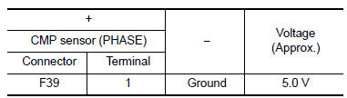
Is the inspection result normal? YES >> GO TO 4.
NO >> GO TO 3.
3.CHECK SENSOR POWER SUPPLY 2 CIRCUIT
Check sensor power supply 2 circuit. Refer to EC-444, "Diagnosis Procedure".
Is inspection result normal? YES >> Perform the trouble diagnosis for power supply circuit.
NO >> Repair or replace error-detected parts.
4.CHECK CMP SENSOR (PHASE) GROUND CIRCUIT
- Turn ignition switch OFF.
- Disconnect ECM harness connector
- Check the continuity between CMP sensor (PHASE) harness connector and ECM harness connector.
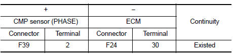
- Also check harness for short to power.
Is the inspection result normal? YES >> GO TO 5.
NO >> Repair or replace error-detected parts.
5.CHECK CMP SENSOR (PHASE) INPUT SIGNAL CIRCUIT
- Disconnect ECM harness connector.
- Check the continuity between CMP sensor (PHASE) harness connector and ECM harness connector.
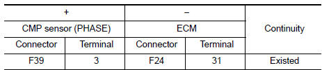
- Also check harness for short to ground and to power.
Is the inspection result normal? YES >> GO TO 6.
NO >> Repair or replace error-detected parts.
6.CHECK CAMSHAFT POSITION SENSOR (PHASE)
Check the camshaft position sensor (PHASE). Refer to EC-282, "Component Inspection [CMP Sensor (PHASE)]".
Is the inspection result normal?
YES >> GO TO 7.
NO >> Replace camshaft position sensor (PHASE). Refer to EM-60, "Removal and Installation".
7.CHECK CAMSHAFT (INT)
Check the following.
- Accumulation of debris to the signal plate of camshaft rear end
- Chipping signal plate of camshaft rear end
Is the inspection result normal? YES >> Check intermittent incident. Refer to GI-39, "Intermittent Incident".
NO >> Remove debris and clean the signal plate of camshaft rear end or replace camshaft. Refer to EM-60, "Removal and Installation".
![Component Inspection [CMP Sensor (PHASE)]](images/books/349/12/index156.jpg)
Component Inspection [CMP Sensor (PHASE)]
1.CHECK CAMSHAFT POSITION SENSOR (PHASE)-1
- Turn ignition switch OFF.
- Loosen the fixing bolt of the sensor
- Disconnect camshaft position sensor (PHASE) harness connector.
- Remove the sensor.
- Visually check the sensor for chipping.
Is the inspection result normal? YES >> GO TO 2.
NO >> Replace camshaft position sensor (PHASE). Refer to EM-60, "Removal and Installation".
2.CHECK CAMSHAFT POSITION SENSOR (PHASE)-2
Check the resistance camshaft position sensor (PHASE) terminals as per the following.
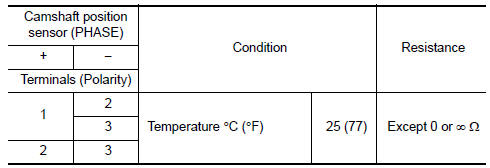
Is the inspection result normal? YES >> INSPECTION END
NO >> Replace camshaft position sensor (PHASE). Refer to EM-60, "Removal and Installation".
 P0335 CKP Sensor (POS)
DTC Logic
DTC DETECTION LOGIC
NOTE:
If DTC P0340 is displayed with DTC P0643, first perform the trouble
diagnosis for DTC P0643. Refer to EC-
353, "DTC Logic".
DTC No.
CONSU ...
 P0420 Three way catalyst function
DTC Logic
DTC DETECTION LOGIC
The ECM monitors the switching frequency ratio of air fuel ratio (A/F)
sensor 1 and heated oxygen sensor 2.
A three way catalyst (manifold) with high oxygen storage ...
Other materials:
Vehicle recovery (freeing a stuck vehicle)
Front (if so equipped)
Do not use the hook to tow the vehicle.
Remove the cover bumper bracket using a
flat screwdriver or any flat tool.
To protect the bumper body, place a piece of
cloth between the tool and the vehicle.
The tool used should be inserted by the
lower portion of t ...
Steering gear and linkage
Exploded View
REMOVAL
Steering gear assembly
Front suspension member
Front
Removal and Installation
REMOVAL
Set steering wheel to the straight-ahead position.
Remove floor cover (1).
Lower shaft assembly (2).
Remove the lower shaft assembly bo ...
Rear disc brake
Exploded View
Sliding pin bolt
Bushing
Cap
Bleeder valve
Cylinder body
Piston seal
Piston
Piston boot
Sliding pin boot
Torque member
Apply rubber grease
Apply brake fluid
Disassembly and Assembly
DISASSEMBLY
Place a wooden block as shown, and blow air from union ...
