Nissan Sentra Service Manual: Brake pedal
Inspection
BRAKE PEDAL HEIGHT
Check the brake pedal height (H1) between the dash lower panel (1) and the brake pedal upper surface.
Brake pedal height (H1) : Refer to BR-54, "Brake Pedal".
CAUTION:
Check the brake pedal height with the floor trim removed.
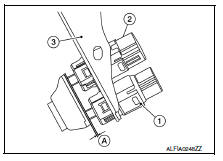
STOP LAMP SWITCH AND BRAKE PEDAL POSITION SWITCH
Check the clearance (A) between the switch assembly bracket (3), the stop lamp switch (2) and the brake pedal position switch (if equipped) (1).
Clearance (A) : Refer to BR-54, "Brake Pedal".
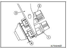
STOP LAMP SWITCH AND BRAKE PEDAL POSITION SWITCH
Check the clearance (A) between the switch assembly bracket (3), the stop lamp switch (2) and the brake pedal position switch (if equipped) (1).
Clearance (A) : Refer to BR-54, "Brake Pedal".
CAUTION:
The stop lamp must turn off when the brake pedal is released.
NOTE:
Pull the brake pedal pad to check that both the stop lamp switch (2) and brake pedal position switch (1) contact ends to brake pedal bracket (3) clearance (A) are within specification.
BRAKE PEDAL PLAY
Check that brake pedal play does not exist.
DEPRESSED BRAKE PEDAL HEIGHT
Check the brake pedal height (H2) between the dash lower panel (1) and the brake pedal upper surface when depressing the brake pedal at 490 N (50 kg, 110 lb) while turning engine ON.
Depressed brake pedal height (H2) : Refer to BR-54, "Brake Pedal".
CAUTION:
Check the depressed brake pedal height with the floor trim removed.
 Basic inspection
...
 Brake fluid
Inspection
BRAKE FLUID LEVEL
Make sure that the brake fluid level in the reservoir tank is between
the MAX and MIN lines.
Visually check around the reservoir tank for brake fluid leakage.
I ...
Other materials:
P1217 Engine over temperature
DTC Logic
DTC DETECTION LOGIC
NOTE:
If DTC P1217 is displayed with DTC UXXXX, first perform the trouble
diagnosis for DTC UXXXX.
If DTC P1217 is displayed with DTC P0607, first perform the trouble
diagnosis for DTC P0607. Refer
to EC-350, "DTC Logic".
If the cooling fan ...
Glass lid
Exploded view
Glass lid
Roof panel
Front
Removal and installation
Removal
Caution:
After installing glass lid, check gap/height adjustments and
operation to make sure there is no malfunction.
Handle glass lid with care to prevent damage.
Open sunshade (1), then close ...
P0037, P0038 HO2S2 Heater
DTC Logic
DTC DETECTION LOGIC
DTC No.
CONSULT screen terms
(Trouble diagnosis content)
DTC detecting condition
Possible cause
P0037
HO2 HTR (B1)
(HO2S heater control circuit
low bank 1 sensor 2)
The current amperage in the heated oxygen sensor
2 heater ci ...
