Nissan Sentra B18 (2020-2025) Service Manual: Belt and Pulleys
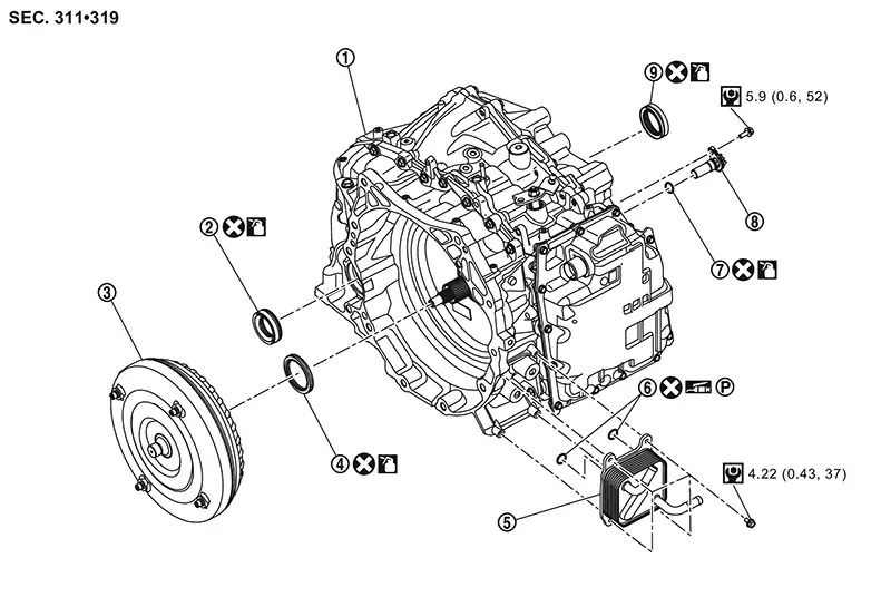
Exploded View
Exploded View
|
|
Transaxle assembly |
|
Differential side oil seal |
|
Torque converter |
|
|
Converter housing oil seal |
|
CVT oil warmer |
|
O-ring |
|
|
O-ring |
|
Primary speed sensor |
|
Differential side oil seal |
|
|
: Always replace after every disasembly. |
||||
|
|
: N·m (kg-m, in-lb) |
||||
|
|
: Apply CVT fluid |
||||
|
|
: Apply petroleum jelly |
||||


|
|
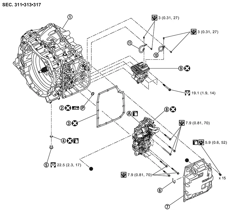
Transaxle assembly |
|
Electric oil pump gasket |
|
Control valve cover gasket |
|
|
O-ring |
|
Drain plug |
|
Clip |
|
|
Control valve cover |
|
Control valve |
|
Electric oil pump |
|
|
Electric oil pump harness (black) |
|
Electric oil pump harness (red) |
||
|
|
O-ring of terminal assembly |
||||
|
|
: Indicates that the part is connected at points with same symbol. |
||||
|
|
: Always replace after every disassembly. |
||||
|
|
: N·m (kg-m, ft-lb) |
||||
|
|
: N·m (kg-m, in-lb) |
||||
|
|
: Apply CVT fluid |
||||
|
|
: Apply petroleum jelly |
||||


|
|
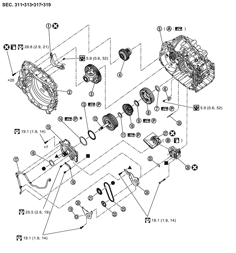
Baffle plate C |
|
Converter housing |
|
Differential assembly |
|
|
Reduction gear assembly |
|
Transaxle assembly |
|
Input speed sensor |
|
|
Thrust bearing |
|
Planetary carrier assembly |
|
Thrust bearing |
|
|
Sun gear |
|
Thrust bearing |
|
Forward clutch assembly |
|
|
Thrust bearing |
|
Bearing race |
|
Dummy cover |
|
|
Thrust bearing |
|
CVT fluid temperature sensor |
|
Oil pump bracket |
|
|
Magnet |
|
Baffle plate A |
|
Drive sprocket |
|
|
Drive sprocket |
|
Chain |
|
Baffle plate B |
|
|
Snap ring |
|
Oil pump |
|
Oil strainer |
|
|
Retaining pin | ||||
|
|
Converter housing installation surface of the transaxle case |
|
O-rings |
||
|
|
: Indicates that the part is connected at points with same symbol. |
||||
|
|
: Always replace after every disassembly. |
||||
|
|
: N·m (kg-m, ft-lb) |
||||
|
|
: N·m (kg-m, in-lb) |
||||
|
|
: Select with proper thickness |
||||
|
|
: Apply CVT fluid |
||||
|
|
: Apply petroleum jelly |
||||
|
|
: Apply Loctite 5460 or equivalent |
||||


|
|
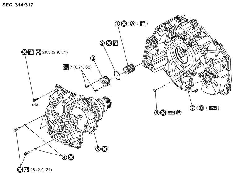
CVT fluid filter |
|
O-ring |
|
CVT fluid filter cover |
|
|
O-ring |
|
Sub-assembly (side cover, belt and pulleys) |
|
O-ring |
|
|
Transaxle assembly |
||||
|
|
Grommet seal |
|
Side cover installation surface of the transaxle case |
||
|
|
: Always replace after every disassembly. |
||||
|
|
: N·m (kg-m, ft-lb) |
||||
|
|
: N·m (kg-m, in-lb) |
||||
|
|
: Apply CVT fluid |
||||
|
|
: Apply petroleum jelly |
||||
|
|
Apply Loctite 5460 or equivalent |
||||
Disassembly and Assembly
Disassembly and Assembly
DISASSEMBLY
CAUTION:
Write down the serial number of new control valve.
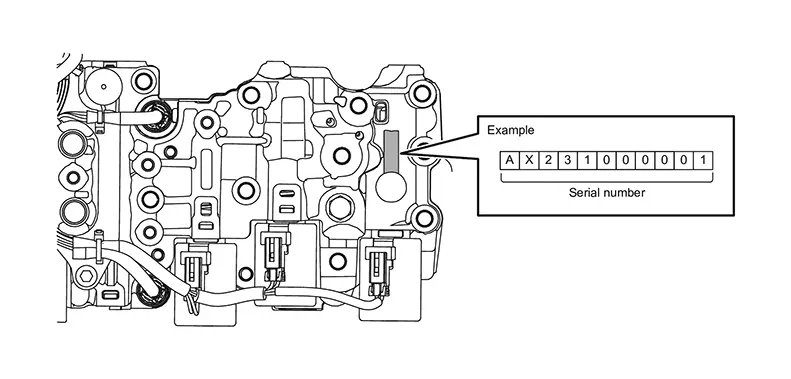 Note:
Note: 
-
When the new control valve is supplied with CD, do not throw CD away, because it may be used during learning after installation.
-
When replacing the control valve, the sticker
 supplied with the new
control valve must
be attached along with data rewriting.
supplied with the new
control valve must
be attached along with data rewriting.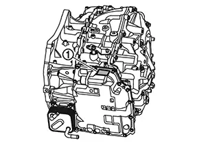
Remove the drain plug from transaxle case and then drain the CVT fluid. Refer to Removal and Installation.
Remove the transaxle assembly from the Nissan Sentra vehicle. Refer to Removal and Installation.
Remove drain plug O-ring.
Maintain the same posture as on the
Nissan Sentra vehicle. Note:
Use plastic or wood blocks to stabilize the transaxle assembly on the work bench if needed.
Remove torque converter from transaxle
assembly. Note:
Wipe out remaining CVT fluid in torque converter.
CAUTION:
-
While removing torque converter, never damage the bush in the sleeve of torque converter.
-
Completely drain CVT fluid from torque converter by tilting right and left several times until no fluid coming out.
Remove primary pulley speed sensor
mounting bolt  and then remove primary pulley speed sensor .
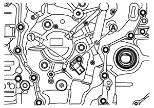
Remove O-ring
from primary pulley speed sensor. 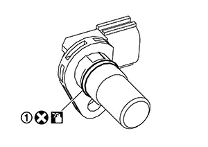
Remove CVT oil warmer mounting bolts
and then remove CVT oil warmer . 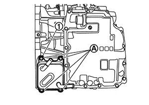
Remove O-rings
from CVT oil warmer. 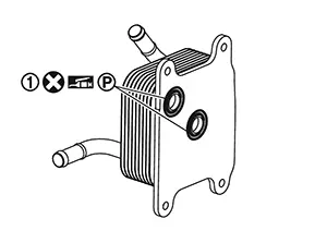
Remove the control valve cover mounting
bolts ( 15 pieces) and then remove control valve cover .
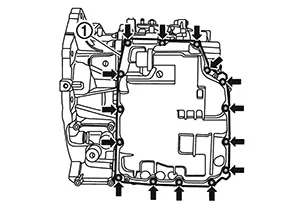
Remove clip
from terminal assembly. 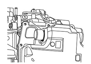
Remove the terminal assembly
from control valve cover. 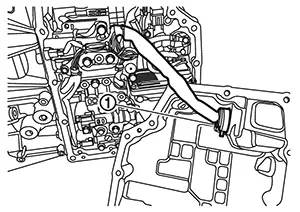
Remove the control valve cover gasket . 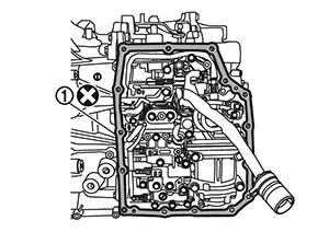
Disconnect CVT fluid temperature sensor
harness connector . 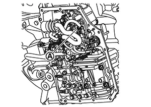
Remove the CVT fluid sensor harness according to the following procedure.
-
Remove harness from the notch
of the control valve plate. -
Remove harness from between the bolt
 and the bracket
  .
.
Remove electric oil pump harness mounting
bolts . 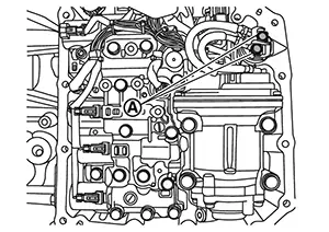
Remove electric oil pump mounting bolts
and then remove electric oil pump
and electric oil pump harness from transaxle assembly. 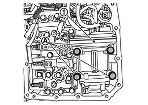
Disconnect electric oil pump harness
connector from electric oil pump .
Remove electric oil pump harness mounting
bolts , and then remove electric oil pump harnesses (red
and black  ).
). 
Remove electric oil pump gasket. 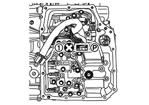
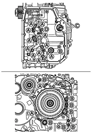
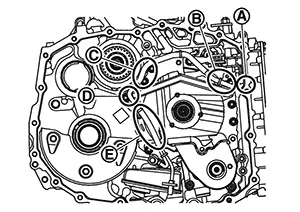
Remove control valve
with mounting bolts , ,
and  (15 pieces in all).
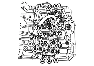
CAUTION:
Do not mix 4 types of bolts which were removed from control valve, and keep them separately.
|
Bolt |
Bolt length mm (in) |
Number of bolt |
|---|---|---|
|
|
68 (2.68) |
6 |
|
|
76 (2.99) |
2 |
|
|
87 (3.43) |
4 |
|
94 (3.70) |
3 |
Remove the control valve  from transaxle case.
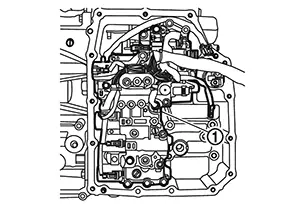
Install the control valve cover mounting
bolts () temporarily at the 4 points. 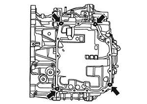
Place transaxle assembly with the converter housing side as the top.
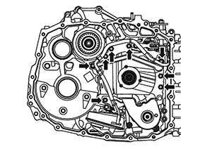
Remove converter housing mounting bolts
( 20 pieces). 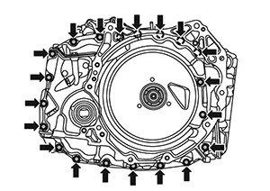
Remove converter housing by applying slide
hammer [SST: KV315J0610 (NI-25721-A)], slide hammer nut and bolt kit
[SST: KV315J0630 (NI-50255-UPD)] and J hook case separator [SST:
KV315J0620 (NI-51923)] to three positions with arrow marks (). 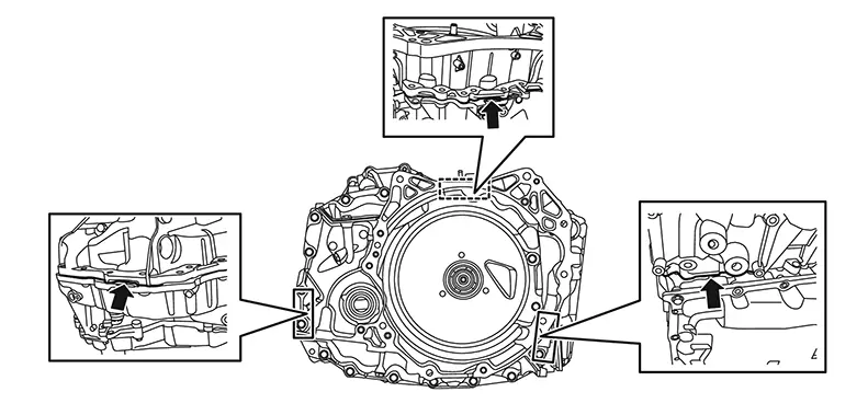
Remove mounting bolts (
3 pieces) and then remove the baffle plate C from the converter
housing. 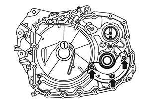
Check that retaining pin of manual shaft locates on the original
position. 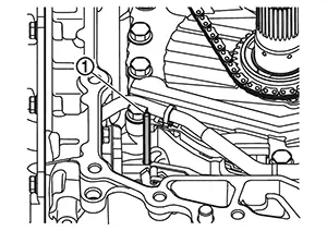
CAUTION:
Retaining pin can slip out during movement of the transaxle assembly while converter housing is removed.
Remove reduction gear assembly and differential assembly
together. 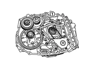
CAUTION:
Handle parts with care. Never reuse damaged parts, if dropped.
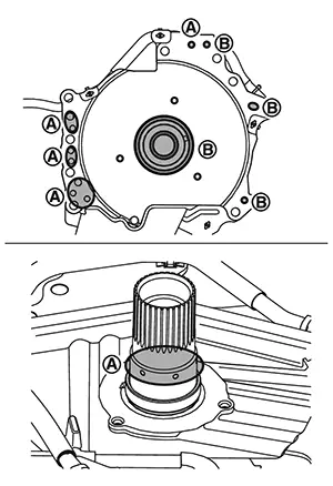
Remove converter housing oil seal from converter housing using a
suitable tool
(A). 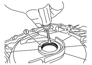
Remove differential side oil seal from converter housing using a
suitable tool
(A). 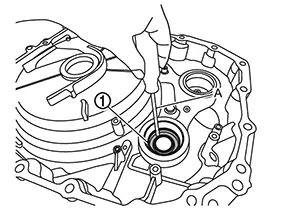
Remove differential side oil seal from transaxle assembly using a
suitable tool
(A). 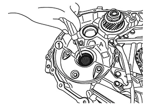
Remove mounting bolt
of baffle plate A and then remove baffle plate A . 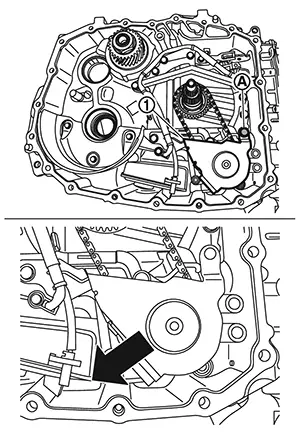 Note:
Note:
Slide the baffle plate A to the direction arrow in the figure.
Remove magnet
from the baffle plate A. 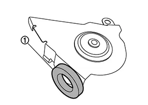
While expanding snap ring
of the oil pump with snap ring pliers, lift driven sprocket
and remove it. 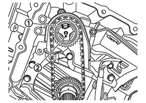
Remove chain ,
drive sprocket and driven sprocket  all together.
Remove oil pump snap ring . 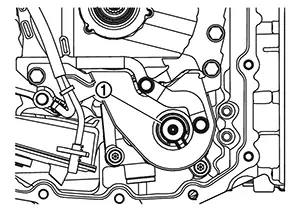
Remove thrust washer from dummy cover. 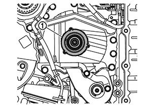
Remove bracket mounting bolts
and then remove bracket . 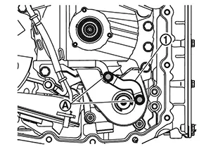
Disconnect the speed sensor connector
and remove the fluid temperature sensor from the oil strainer. 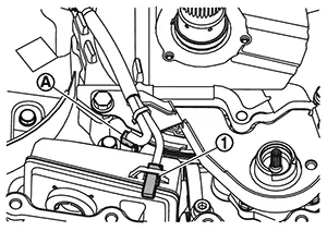
Rotate the input shaft
by hand to check the input shaft rotational characteristics. 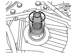 Note:
Note:
-
Memorize the input shaft rotational characteristics.
This is used as a reference after the new sub-assembly, forward clutch assembly, dummy cover were installed.
-
Perform in the shift position except 'P' position.
Remove mounting bolts
of dummy cover and baffle plate B. 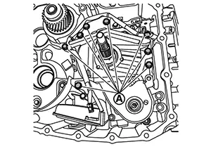
CAUTION:
Do not damage the fluid temperature sensor harness by tool when removing the bolts.
Remove the dummy cover , baffle plate B
and CVT fluid temperature sensor
all together.
CAUTION:
-
Do not remove the fluid temperature sensor from the dummy cover and the baffle plate B.
-
Never lift input shaft because it causes lifting clutch pack assembly out.
-
Pay attention to the points below to prevent damaging the harness or harness clips. Replace with new fluid temperature sensor assembly if it has been damaged.
-
Do not cut harness clips.
-
Do not pull the harness with excessive force.
-
Remove the bearing race from the dummy cover.
CAUTION:
-
The bearing race may remain on the forward clutch assembly be sure to remove it.
-
Never remove lathe cut seals
from dummy cover. These seals will
be reused.
Remove input speed sensor mounting bolt
and then remove input speed sensor . 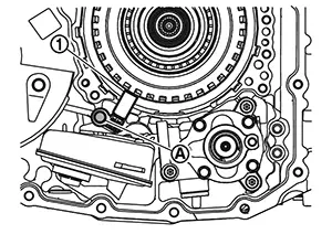
CAUTION:
Never impact the input speed sensor.
Remove oil pump mounting bolts
and then remove oil pump and oil strainer
together. 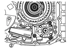
Remove thrust bearing
from forward clutch assembly. 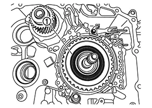
Remove forward clutch assembly
from transaxle case. 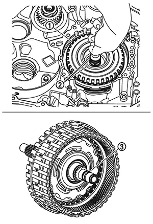
CAUTION:
Never handle lathe cut seals and on the input shaft when removing clutch
assembly. These seals will be reused.
Remove thrust bearing
which exists between forward clutch assembly and sun gear. 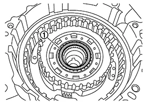 Note:
Note:
The thrust bearing has two sides. Memorize or take a note of the original surface before removing for assembling procedure.
Remove sun gear
from planetary carrier. 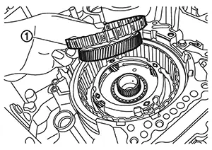
Remove the thrust bearing
between the sun gear and the planetary carrier. 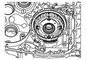 Note:
Note:
The thrust bearing has two sides. Memorize or take a note of the original surface before removing for assembling procedure.
Remove planetary carrier
from transaxle case. 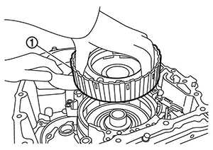
Remove thrust bearing
from planetary carrier. 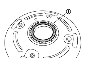 Note:
Note:
-
The thrust bearing has two sides. Memorize or take a note of the original surface before removing for assembling procedure.
-
Thrust bearing may remain on the transaxle case.
Rotate the output gear by hand to check
the output gear rotational characteristics. 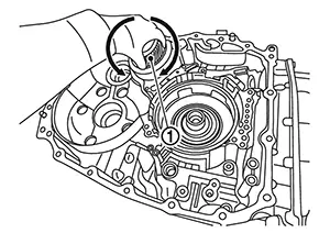 Note:
Note:
-
Memorize the output gear rotational characteristics.
This is used as a reference after the new sub-assembly were installed.
-
Perform in the shift position except 'P' position.
Make sure rust and foreign materials have
been cleaned off of dowel pins
and receiving holes . Note:
Use small wire brush or similar tool at the inside surface of dowel pin holes. Never scrape transaxle case mating surfaces.
Thoroughly clean the mating surfaces of
the transaxle case and torque converter housing. Note:
-
A plastic scraper can be used.
-
Remove the old sealant from the mating surfaces.
CAUTION:
-
Never use sanding discs, similar abrasive tools, or metal blades.
-
Use parts cleaner or equivalent solvent and lint-free paper only.
-
Make sure the parts cleaner or solvents used are compatible with local regulations.
-
Prevent debris from entering in the transaxle case.
Remove the control valve cover mounting
bolts ( 4 pieces) and then remove control valve
cover.
Cleaning mating surface of control valve
and control valve hydraulic circuits
with parts cleaner and blowing air.
Check holes
for blowing air.
Clean around
area.
CAUTION:
-
When blowing air, be careful not to get foreign materials in the eyes.
-
Never blow air in the clutch circuit
.
Clean hydraulic circuits
of converter housing with parts cleaner and blowing air.
Check holes
for blowing air.
CAUTION:
When blowing air, be careful not to get foreign materials in the eyes.
Clean hydraulic circuits
of dummy cover with parts cleaner and blowing air.
Check holes
for blowing air.
CAUTION:
When blowing air, be careful not to get foreign materials in the eyes.
Temporarily install converter housing to
transaxle case by using only three of old converter housing mounting
bolts to tighten them in a triangular shape. 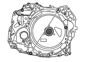
Install the control valve cover mounting
bolts () temporarily at the 4 points.
Place transaxle assembly with converter housing side as the bottom.
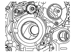
Remove side cover mounting bolts (
18 pieces). 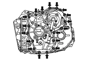
Loosen the pulley retainer mounting bolts
( 6 pieces) approximately 3 turns. 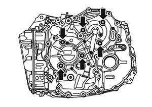
CAUTION:
Do not remove the bolts completely.
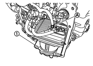
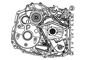
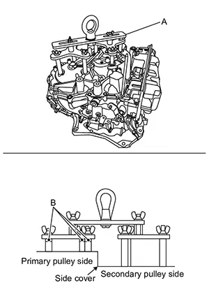
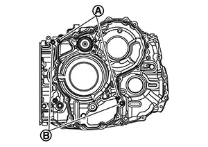
Shock three parts ()
of the side cover with the slide hummer [SST: KV315J0610 (NI-25721-A)]
and the slide hammer nut and bolt kit [SST: KV315J0630 (NI-50255-UPD)]
to cut the sealant material at the joint between the transaxle and the
side cover. 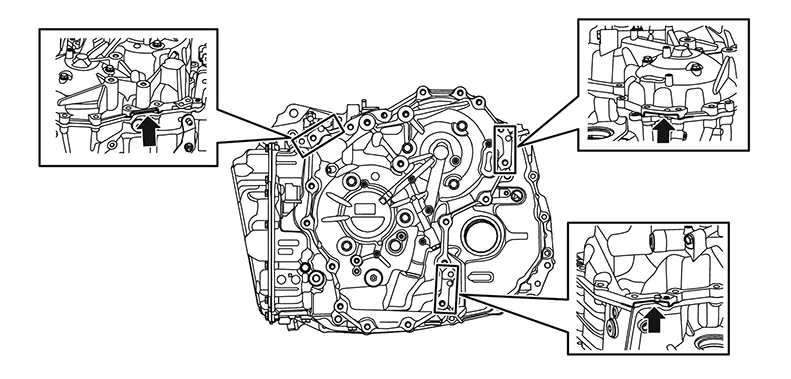
Attach the locator guide pins [SST:
KV31500300 (NI-52272)] to the specified bolt holes . 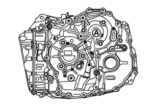
Remove pulley retainer mounting bolts
( 2 pieces). 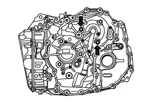
Install long shafts (A) of CVT lifting
fixture (SST: NI-52082). 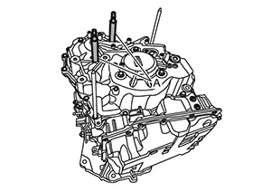
Remove pulley retainer mounting bolt (). 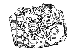
Install long shaft (A) of CVT lifting
fixture (SST: NI-52082). 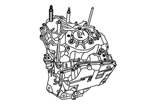
Remove pulley retainer mounting bolts
( 2 pieces). 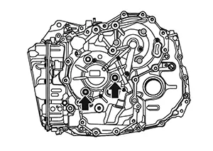
Install medium shafts (A) of CVT lifting
fixture (SST: NI-52082). 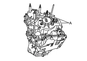
Remove pulley retainer mounting bolt (). 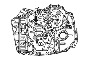
Install medium shaft (A) of CVT lifting
fixture (SST: NI-52082). 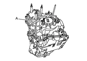
Install CVT lifting fixture (SST: NI-52082) (A) and spacer for CVT universal lifting (SST: NI-52082-2) (B) to bearing retainer mounting hole.
CAUTION:
Install CVT lifting fixture properly.
Lift up the CVT lifting fixture with crane
(A) to remove the sub-assembly (side cover , belt and pulleys )
from the transaxle case. 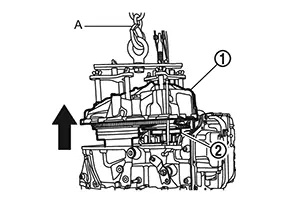
Remove the side cover assembly guide pins from the transaxle case.
Remove O-ring . 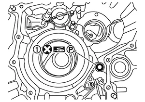
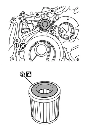
Remove the CVT fluid filter cover mounting
bolts and then remove the CVT fluid filter cover . 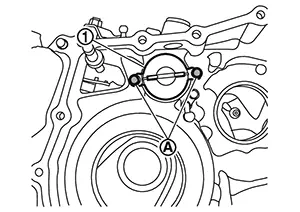
Remove O-ring
from CVT fluid filter cover. 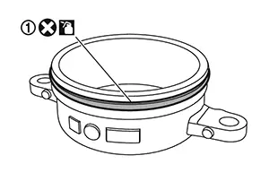
Remove CVT fluid filter . 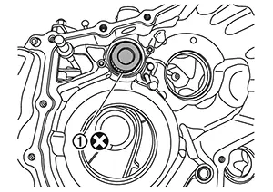
CAUTION:
Grommet seal of oil filter may remain on the transaxle case be sure to remove it.
Completely remove old liquid gasket from
transaxle case. Note:
-
A plastic scraper can be used.
-
Remove the old sealant from the mating surfaces.
CAUTION:
-
Never use sanding discs, similar abrasive tools, or metal blades.
-
Use parts cleaner or equivalent solvent and lint-free paper only.
-
Make sure the parts cleaner or solvents used are compatible with local regulations.
-
Prevent debris from entering in the transaxle case.
Clean around oil filter
and hydraulic circuits
with parts cleaner and compressed air.
Warning:
Wear eye and face protection when using compressed air and cleaning fluid.
CAUTION:
-
Regulate air pressure up to a maximum of 517 kPa (5.27 kg/cm2, 75 psi).
-
Prevent foreign materials from entering the transaxle case.
Clean around oil filter cover
with parts cleaner. 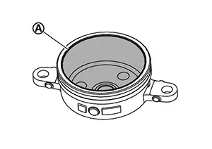
Warning:
Wear eye and face protection when using cleaning fluid.
ASSEMBLY
Install oil filter .
CAUTION:
-
Never reuse the oil filter.
-
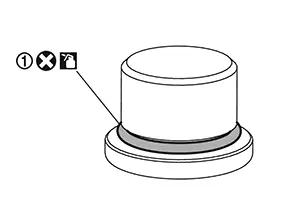
Apply CVT fluid to the grommet seal
.
Install O-ring
to CVT fluid filter cover.
CAUTION:
-
Never reuse the O-ring.
-
Apply CVT fluid to the O-ring.
Install CVT fluid filter cover and then tighten CVT fluid filter
cover mounting
bolts to the specified torque. Refer to Exploded View.
Install O-ring .
CAUTION:
-
Never reuse the O-ring.
-
Apply petroleum jelly to O-ring.
Install CVT lifting fixture (SST: NI-52082)and spacer for CVT universal lifting (SST: NI-52082-2) to new sub-assembly (side cover, belt and pulleys).
CAUTION:
As soon as removing a bearing retainer mounting bolt, install a shaft of CVT lifting fixture. (Exchange one by one. If all bearing retainer mounting bolts are removed at once, CVT lifting fixture may not be installed well.)
Apply Loctite 5460 or equivalent on the transaxle case installation surface of the side cover.
CAUTION:
-
Completely remove all moisture, oil and old sealant, etc. from the transaxle case and side cover mounting surfaces.
-
The sealant width is 2 - 3 mm (0.08 - 0.12 in).
-
Check that the starting point and the ending point are about the middle between the bolts. The overlap both ends of the bead by 3 - 5 mm (0.12 - 0.20 in)
. -
Be careful not to contact or contaminate the sealant. If the sealant has been disturbed or contaminated in any way before case assembly, thoroughly clean the mating surfaces of the transaxle case.
Attach the locator guide pins [SST:
KV31500300 (NI-52272)] to the specified bolt holes . Note:
Guide pins must be placed next to dowel pins .
Set manual lever position to 'P'. 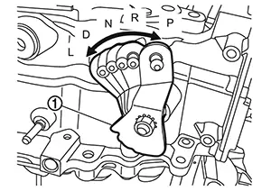
Lift up the CVT lifting fixture with crane
(A) and then install sub-assembly (side cover , belt and pulleys )
to transaxle case. 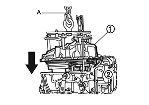
CAUTION:
-
Apply CVT fluid to primary front bearing and secondary front bearing before assembling.
-
Never drop parts with care. If dropped, parts may be damaged and can not be reused.
When installing side cover, insert parking rod
to parking pawl area .

Confirm the parking rod operation with the following procedure.
-
Rotate the manual lever
counter clockwise and check that all
detents for each of the P-R-N-D-L are detect. -
If the lever does not rotate or if all detents are not detect, lift the sub-assembly and remove all sealant, and repeat from step 5.
Set the manual lever position to ‘L’ after the
confirmation. 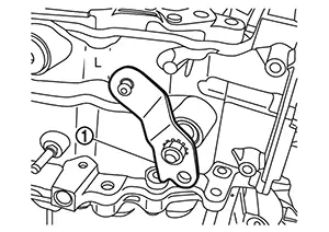
Remove the locator guide pins [SST: KV31500300 (NI-52272)].
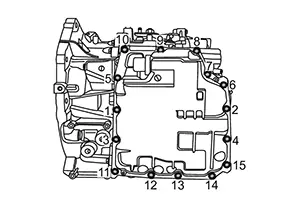
Tighten side cover mounting bolts to the
specified torque in numerical order shown in the figure. Refer to Exploded View. 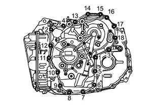
CAUTION:
-
Never reuse the side cover mounting bolts.
-
Apply CVT fluid to the mounting bolts.
-
Use the bolts with pilot shape
at the end.
Install O-ring to pulley retainer bolt.
CAUTION:
-
Never reuse the O-ring.
-
Never reuse the pulley retainer bolt.
-
Do not apply CVT fluid to this O-ring.
Remove the part (A) of CVT lifting fixture
shown in the figure. 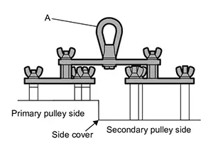
As soon as removing one shaft of CVT lifting fixture, install one pulley retainer mounting bolt described in the step 14.
Exchange them one by one. If all shafts are removed at once, it is difficult to find out bolt hole inside of the sub-assembly, and the pulley retainer mounting bolts may not be installed well.
Tighten bearing retainer mounting bolts
( 6 pieces) to the specified torque. Refer to Exploded View. 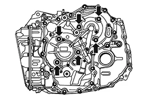
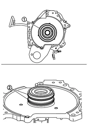
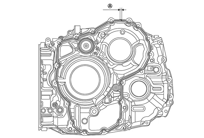
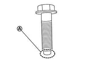
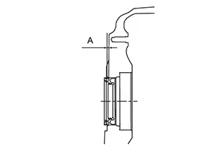
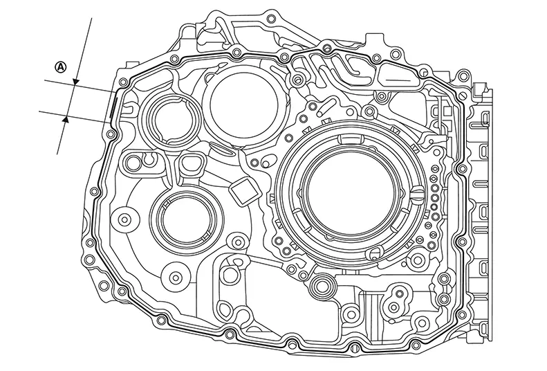
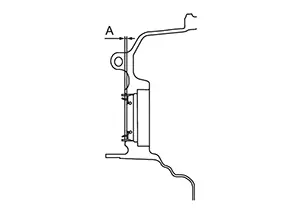
Install differential oil seal to the transaxle case with seal
installer [SST:
KV31500800 (NI-52283)] and driver handle [SST: ST35325000 (NI-8092)]
until it is flush. 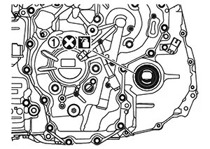
CAUTION:
-
Never reuse differential oil seal.
-
Apply the CVT fluid to the differential oil seal.
Height or depth (A) of differential side oil seal from the surface : 1.8 ± 0.5 mm (0.071 ± 0.020 in)
Place transaxle assembly with the converter housing side as the top.
Remove temporarily installed converter housing.
Check the rotational smoothness of the
output gear with the following procedure.
-
Rotate the output gear by hand to confirm that the gear and pulleys installed in the case rotate normally.
-
If the rotational characteristic worse than before the sub-assembly was replaced, perform the following.
-
Remove the sub-assembly from the transaxle case.
-
Wipe and clean the sealant completely from both the transaxle case rim and side cover rim.
-
Restart sub-assembly installation from Step 5.
-
CAUTION:
Never insert fingers between the output gear and the transaxle case .
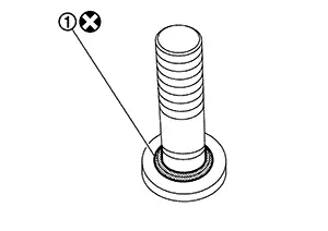
Install thrust bearing to the transaxle assembly. 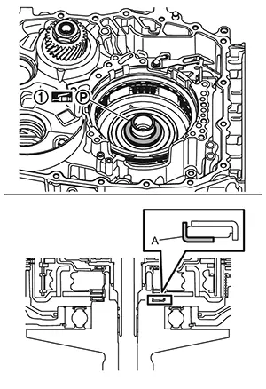
CAUTION:
-
Make sure thrust bearing is installed in the correct direction.
-
Apply petroleum jelly to the thrust bearing to hold it in place on the primary pulley.
-
Assemble with the colored surface (A) side down.
Install planetary carrier to the transaxle assembly. 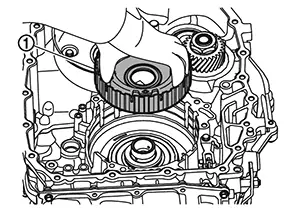
Install thrust bearing to planetary carrier. 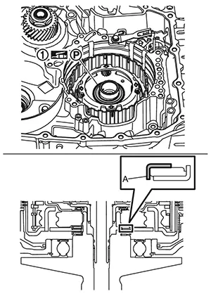
CAUTION:
-
Make sure thrust bearing is installed in the correct direction.
-
Apply petroleum jelly to the thrust bearing to hold it in place on the planetary carrier.
-
Assemble with the colored surface (A) side up.
Install the sun gear to the transaxle assembly.
Install thrust bearing to sun gear. 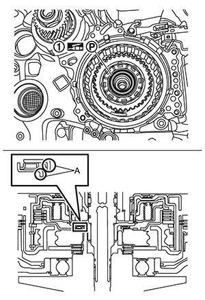
CAUTION:
-
Make sure thrust bearing is installed in the correct direction.
-
Apply petroleum jelly to the thrust bearing to hold it in place on the sun gear.
-
Install the thrust bearing with the raised edge (A) side facing down.
Using a suitable tool (A) gently align the
layers of the forward clutch assembly . 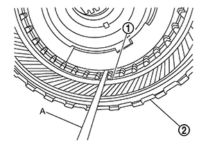
Install forward clutch assembly to the transaxle assembly.
CAUTION:
-
Check that the lathe cut seals
are in the specified positions
before clutch assembly installation. -
Check that the lathe cut seal
is in the specified position
before clutch assembly installation. -
Lathe cut seal must be in its appropriate slot. Carefully reposition the seal as necessary.
-
Gently jiggle the input shaft until the forward clutch assembly seats below case lip.
-
If the forward clutch assembly does not seat, rotate back and forth from the input shaft and jiggle.
-
If the clutch pack still does not seat, repeat from step 27.
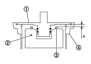
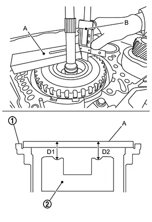
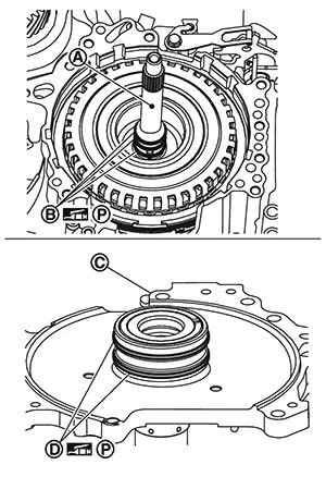
Calculate total end play with the following procedure. (thrust bearing selection)
CAUTION:
The total end play (A) must always be adjusted
between the dummy cover and the forward clutch drum when a new sub-assembly is
installed.
|
|
: Thrust bearing and bearing race |
|
|
: Transaxle case |
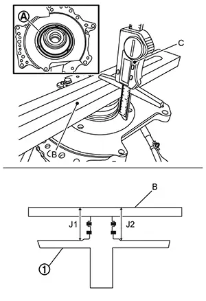
Clean the dummy cover surfaces
that contact the transaxle case and thrust beaning. 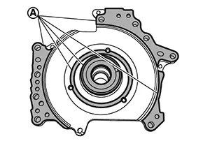
Measure the average distance (J) at two
different positions
of the dummy cover .
|
Average distance (J) |
: (J1 + J2)/2 |
|
B |
: Gauge block [SST: KV315J0400 (NI-50271)] |
|
C |
: Digital Depth Gauge [SST:KV315J0500 (NI-50272)] |
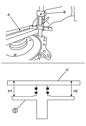
Measure the average distance (H) from the
edge of the dummy cover to the installation surface on the transaxle
case.
|
Average distance (H) |
: (H1 + H2)/2 |
|
A |
: Gauge block [SST: KV315J0400 (NI-50271)] |
|
B |
: Digital Depth Gauge [SST:KV315J0500 (NI-50272)] |
Calculate the distance (G) from the dummy cover.
Distance (G) : J – H
Measure the average distance (D) from the
gauge block (A) placed on the transaxle case to the forward clutch
drum .
|
Average distance (D) |
: (D1 + D2)/2 |
|
A |
: Gauge block [SST: KV315J0400 (NI-50271)] |
|
B |
: Digital Depth Gauge [SST:KV315J0500 (NI-50272)] |
CAUTION:
-
The forward clutch is 2 - 3 mm (0.08 - 0.12 in) below the dummy cover surface.
-
If the gap is less than 2 - 3 mm (0.08 - 0.12 in), the component parts may be improperly installed. Restart forward clutch assembly installation from Step 28.
-
If the gap is more than 2 - 3 mm (0.08 - 0.12 in), the component parts may be missing or damaged.
-
When the measurement value D - T is not within the limit shown in the table blow, repeat Step 22 to 28, because the parts of forward clutch, etc. may not be assembled correctly.
D - T
: 3.82 - 4.84 mm (0.150 - 0.191 in)
“T“ is the thickness of the gauge block.
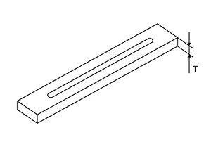
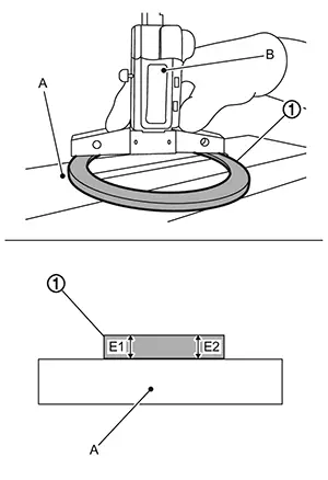
Measure the average plate thickness (E) of
the thrust bearing .
|
average plate thickness (E) |
: (E1 + E2)/2 |
|
A |
: Gauge block [SST: KV315J0400 (NI-50271)] |
|
B |
: Digital Depth Gauge [SST:KV315J0500 (NI-50272)] |
Measure the bearing with the exposed bearings facing down.
Calculate the total end play with the following formula, and choose the appropriate bearing race from table.
Clearance (C) = (D) - (T) + (G) - (E)
 Note:
Note:
-
“T“ is the thickness of the gauge block.
-
Chosen bearing race will be use at the later step 42.
|
Clearance (C) |
Bearing race thickness |
|
1.29 - 1.50 mm |
1.00 mm |
|
1.51 - 1.70 mm |
1.20 mm |
|
1.71 - 1.90 mm |
1.40 mm |
|
1.91 - 2.10 mm |
1.60 mm |
|
2.11 - 2.30 mm |
1.80 mm |
|
2.31 - 2.50 mm |
2.00 mm |
Install the thrust bearing to the forward clutch assembly. 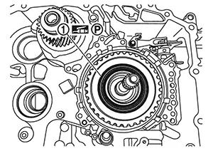
CAUTION:
-
Apply petroleum jelly when installing the thrust bearing.
-
Pay attention to the direction of the thrust bearing when installing it. Install the thrust bearing with the exposed bearings facing up.
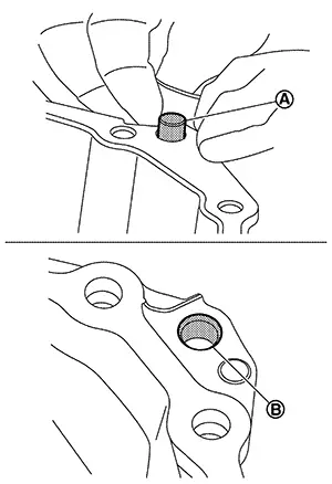
Install the oil strainer to the oil pump . Note:
Attach the oil strainer to the oil pump and then twist the oil strainer to lock.
CAUTION:
-
Never reuse oil pump and oil strainer.
-
Apply CVT fluid to the O-rings
of oil strainer when
installation.
Confirm that one-way valve is attached to the oil strainer
correctly. 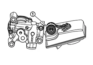
CAUTION:
-
Check if one-way valve is assembled in the direction that "+" shape
can be seen. -
Push in the one-way valve completely until it reaches to the end.
Install oil pump and oil strainer
to transaxle case. Tighten mounting bolts
of oil pump to the specified torque. Refer to Exploded View.
CAUTION:
Insert the one-way valve of oil strainer into the bore of the transaxle case, and then push in the oil strainer and oil pump together until they seats onto the transaxle case completely.
Install input speed sensor , and then tighten input speed sensor
mounting bolt
to the specified tightening torque. Refer to Exploded View.
CAUTION:
-
Clean the input speed sensor before installation.
-
Wipe off any debris from the surface of the input speed sensor.
-
Never impact the input speed sensor.
Install the bearing race to the dummy cover. 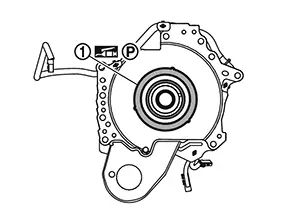 Note:
Note:
Use now the bearing race selected at step 36.
CAUTION:
-
Make sure the tabs fit into the holes on the dummy cover.
-
Apply petroleum jelly to the bearing race.
Install dummy cover ,
baffle plate B and CVT fluid temperature sensor
all together. And then temporarily tighten the mounting bolt . 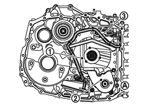
Tighten dummy cover and baffle plate B
mounting bolts ( 8 pieces) to the specified torque. Refer to Exploded View.
CAUTION:
-
Apply petroleum jelly to the input shaft's
lathe cut seals before
installing the dummy cover
to the transaxle case.
-
Check that the input shaft's
lathe cut seals are in the specified
position. -
Lathe cut seals
(white seals) must be in their
appropriate slots. Carefully reposition seals as
necessary. -
Lathe cut seals
must be in specified positions
during final assembly to prevent drivability
issues. -
Apply petroleum jelly to the dummy cover's
lathe cut seals before
installing the dummy cover
to the transaxle case.
-
Check that the dummy cover's lathe cut seals
are in the specified
positions. -
Lathe cut seals
(white seals) must be in their
appropriate slots. Carefully reposition seals as
necessary. -
Lathe cut seals
must be in specified positions
during final assembly to prevent drivability
issues.
Check the rotational smoothness of the
input shaft with the following procedure.
-
Rotate the input shaft by hand to confirm that the input shaft installed in the case rotate normally.
-
If the rotational characteristic worse than before the was replaced, perform the following.
-
Remove the dummy cover and the parts under the dummy cover.
-
Restart the dummy cover installation from Step 43.
-
Connect harness connector
to the input speed sensor. 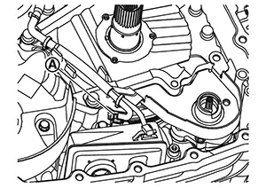
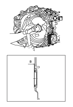
Fix the CVT fluid temperature sensor body
to the oil strainer by the clip . 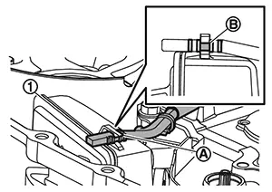 Note:
Note:
Fix the CVT fluid temperature sensor at the center
notch of three notches on the CVT temperature
sensor body.
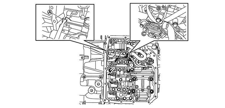
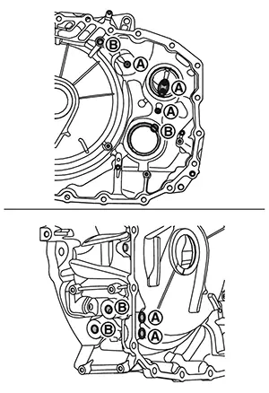
Place the CVT fluid temperature sensor harness with the following procedure.
-
:Put the harness into the control
valve room through the opening of transaxle case.
-
:The harness shall be placed between
the dummy cover and the manual shaft retaining pin.
-
:The harness shall be placed between
the dummy cover and the transaxle case.
CAUTION:
The harness shall not be placed on the bolts.
-
: The harness shall be placed
between the bolt and the dummy cover.
-
 : harness shall be placed between
guide walls on the dummy cover.
: harness shall be placed between
guide walls on the dummy cover.
Install oil pump bracket
and then tighten oil pump bracket mounting bolts
to the specified torque each in numerical order 1 and 2 shown in the
figure. Refer to Exploded View. 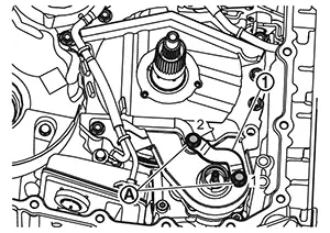
Install thrust washer
to the dummy cover. 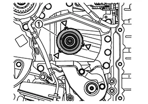 Note:
Note:
Make sure the tabs (  ) fit into the holes.
Install oil pump snap ring . 
Install chain ,
drive sprocket and driven sprocket
all together.
While expanding snap ring
of oil pump with snap ring pliers , fix driven sprocket .
CAUTION:
-
Expand the snap ring, and then push down the driven sprocket until it reaches to the bottom.
-
Release the snap ring and then pull up the driven sprocket until the snap ring locks.
-
Lift driven sprocket and check that it does not come off.
Install magnets
to the baffle plate A.
CAUTION:
-
Clean the magnet before installation. Wipe off any debris from the surface of the magnet.
-
Align the hole of the magnet with the protrusion on the plate.
Remove the dummy cover mounting bolt (). 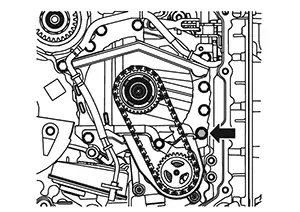
Install baffle plate A
and then tighten baffle plate A mounting bolt
to the specified torque. Refer to Exploded View. 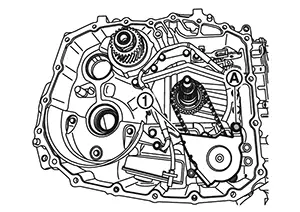 Note:
Note:
Fix the dummy cover, baffle plate A, and baffle plate B together.
Install reduction gear assembly
and differential assembly
together.
CAUTION:
Handle parts with care. Never reuse damaged parts, if dropped.
Check that retaining pin
of manual shaft locates on the original position.
Install baffle plate C
to the converter housing and then tighten baffle plate C mounting bolts
( 3 pieces) to the specified torque. Refer to Exploded View. 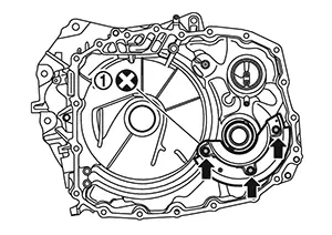
CAUTION:
Never reuse baffle plate C.
Apply Loctite 5460 or equivalent on the converter housing installation surface of the transaxle case.
CAUTION:
-
Completely remove all moisture, oil and old sealant, etc. from the transaxle case and converter housing mounting surfaces.
-
The sealant width is 2 - 3 mm (0.08 - 0.12 in).
-
Check that the starting point and the ending point are about the middle between the bolts. The overlap both ends of the bead
by 25 - 30 mm (0.98 - 1.18
in).
Install converter housing.
CAUTION:
Completely remove all moisture, oil and old sealant, etc. from the transaxle case and converter housing mounting surfaces.
Tighten converter housing mounting bolts
to the specified torque in numerical order shown in the figure. Refer to
Exploded View. 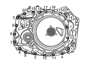 Note:
Note:
Apply CVT fluid to the bolts when installing.
CAUTION:
Never reuse the converter housing mounting bolts.
Install differential side oil seal to the converter housing with seal installer [SST: KV31500900 (NI-52284)] and driver handle [SST: ST35325000 (NI-8092)] until it is flush.
CAUTION:
-
Never reuse differential side oil seal.
-
Apply CVT fluid to differential side oil seal.
Height or depth (A) of differential side oil seal from the surface : 2.2±0.5 mm (0.087±0.020 in)
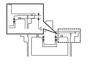
Install converter housing oil seal evenly using the torque
converter seal installer
(SST : NI-53062) (A).
|
Height or depth (B) of converter housing oil seal from the surface |
: 1.0 ± 0.5 mm (0.039 ± 0.020 in) |
CAUTION:
-
Never reuse converter housing oil seal.
-
Apply CVT fluid to the oil seal lip and around the oil seal.
-
Converter housing oil seal pulling direction is used as the reference.
Install O-ring
to drain plug.
CAUTION:
-
Never reuse the O-ring.
-
Apply CVT fluid to the O-ring.
Install drain plug
and then tighten drain plug to the specified torque. Refer to Exploded View. 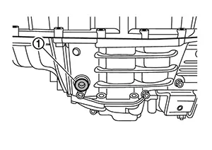
Maintain the same posture as on the Nissan Sentra vehicle.
Remove the control valve cover mounting
bolts ( 4 pieces) and then remove control valve
cover.
Installing the control valve with the following procedure.
-
Manual plate on the transaxle case shall be set to ‘L’ position by rotating the manual lever.
-
Before installing the control valve mounting bolts, check that the manual plate
engages with the manual valve and that the manual shaft rotates
normally.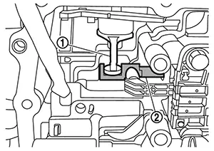
-
Install the control valve
with mounting bolts , , and (15 pieces in all).
Note:Bolt
Bolt length mm (in)
Number of bolt
68 (2.68)
6
76 (2.99)
2
87 (3.43)
4
94 (3.70)
3
Install mounting bolts by hand tightening.
CAUTION:
-
There are 4 types of bolts for control valve installation. Install the bolts to appropriate position.
-
Use new control valve when sub-assembly replacement.
-
-
Tighten all the control valve mounting bolts to the specified torque. Refer to Exploded View.
Install electric oil pump gasket .
CAUTION:
-
Never reuse the oil pump gasket.
-
Apply petroleum jelly to oil pump gasket.
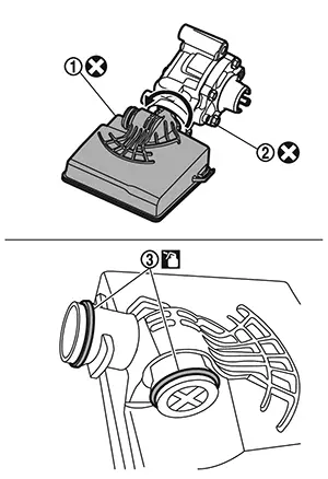
Connect the electric oil pump harness
(black) and electric oil pump harness (red)
to electric oil pump .
Tighten electric oil pump mounting bolts
to the specified torque. Refer to Exploded View. 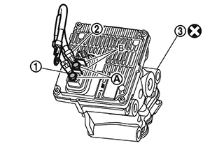
CAUTION:
-
Never reuse the electric oil pump.
-
Connect the electric oil pump harness (black)
and electric oil pump harness
(red) with correct shown in the
figure. -
Never install terminals in the opposite direction.
-
Use the plates (B) as the stopper of the terminals when tightening the bolts.
-
Fix the terminals with the crimped part facing up.
Install electric oil pump
to transaxle case. Tighten mounting bolts
of electric oil pump to the specified torque. Refer Exploded View.
Place the CVT fluid temperature sensor harness with the following procedure.
-
The harness shall pass through the notch
of the plate of control
valve. -
The harness shall pass through between the bolt
and the bracket on the
control valve.
Connect the CVT fluid temperature sensor
harness connector
and electric oil pump harness connector . 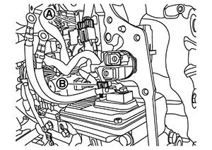
Connect electric oil pump harness (red)
and electric oil pump harness (black)
to terminal connector. Tighten mounting bolts
of electric oil pump harness to the specified torque. Refer to Exploded View. 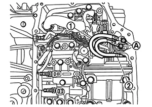
CAUTION:
-
Never install terminals in the opposite direction.
-
When tightening the bolts, hold the terminal connector by hand to prevent it from rotating, and be careful not to damage the terminal connector body and its O-ring.
Install the control valve cover gasket
.
CAUTION:
-
Never reuse the control valve cover gasket.
-
Check that the old gasket is not left stuck to the case or control valve cover.
Install the terminal assembly
to control valve cover. Note:
Turn the terminal assembly until its locator touches the control valve
cover .
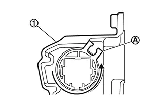
CAUTION:
-
Check that the O-ring is in the specified positions.
-
Apply CVT fluid to the O-ring.
Install clip
to terminal assembly.
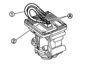
Install the control valve cover. 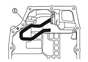 Note:
Note:
The control valve harness must be wired as shown figure.
CAUTION:
Be secure that the harness is not twisted unnecessarily.
Tighten control valve cover mounting bolts to the specified torque in numerical order shown in the figure. Refer to Exploded View.
CAUTION:
Apply CVT fluid to the bolts when installing.
Install O-rings
to CVT oil warmer.
CAUTION:
-
Never reuse the O-ring.
-
Apply petroleum jelly to O-ring.
Install CVT oil warmer
and then tighten oil warmer mounting bolts
to the specified torque. Refer to Exploded View.
Install O-ring
to primary speed sensor.
CAUTION:
-
Never reuse the O-ring.
-
Apply CVT fluid to the O-ring.
Install primary speed sensor
and then tighten primary speed sensor mounting bolt
to the specified tightening torque. Refer to Exploded View.
Install the torque converter to transaxle assembly. Refer to Disassembly and Assembly.
Install the transaxle assembly to the Nissan Sentra vehicle. Refer to Removal and Installation.
Fill the CVT fluid. Refer to Refilling.
After filling the CVT fluid, perform "ADDITIONAL SERVICE WHEN REPLACING CONTROL VALVE". Refer to Description.
Other materials:
B1360 Combination Meter
Dtc Description
DTC Description
DTC DETECTION LOGIC
DTC No.
CONSULT screen terms
(Trouble diagnosis
content)
DTC detection condition
...
Park/neutral Position Switch
Component Inspection
Component Inspection
CHECK PARK/NEUTRAL POSITION
SWITCH-1
Turn ignition switch ON.
Check the voltage between ECM harness
connector and ground.
...
Front Auxiliary Input Jacks
Diagnosis Procedure
Diagnosis Procedure
AUX JACK
CHECK AUX JACK HARNESS CONTINUITY
Ignition switch OFF.
Disconnect AV control unit connector and front
auxiliary input j ...