Nissan Sentra Service Manual: BCM branch line circuit
Diagnosis procedure
1.Check connector
- Turn the ignition switch off.
- Disconnect the battery cable from the negative terminal.
- Check the terminals and connectors of the bcm for damage, bend and loose connection (unit side and connector side).
Is the inspection result normal? Yes >> go to 2.
No >> repair the terminal and connector.
2.Check harness for open circuit
- Disconnect the connector of bcm.
- Check the resistance between the bcm harness connector terminals.
- Without intelligent key system
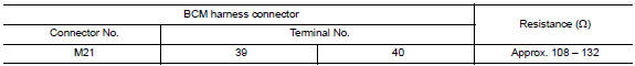
- With Intelligent Key system
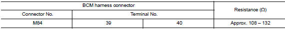
Is the measurement value within the specification? YES >> GO TO 3.
NO >> Repair the BCM branch line.
3.Check power supply and ground circuit
Check the power supply and the ground circuit of the bcm. Refer to the following.
- With intelligent key system: refer to bcs-67, "diagnosis procedure".
- Without intelligent key system: refer to bcs-120, "diagnosis procedure".
Is the inspection result normal? Yes (present error)>>replace the bcm. Refer to the following.
- With Intelligent Key system: Refer to BCS-73, "Removal and Installation".
- Without intelligent key system: refer to bcs-126, "removal and installation".
Yes (past error)>>error was detected in the bcm branch line.
No >> repair the power supply and the ground circuit.
 Hvac branch line circuit
Diagnosis procedure
1.Check connector
Turn the ignition switch off.
Disconnect the battery cable from the negative terminal.
Check the terminals and connectors of the a/c auto amp. For damage ...
 Can communication circuit
Diagnosis procedure
1.Connector inspection
Turn the ignition switch off.
Disconnect the battery cable from the negative terminal.
Disconnect all the unit connectors on CAN communication syste ...
Other materials:
P0604 ECM
DTC Logic
DTC DETECTION LOGIC
DTC No.
CONSULT screen terms
(Trouble diagnosis content)
DTC detecting condition
Possible cause
P0604
ECM
[Internal control module
random access memory
(RAM) error]
Malfunction in the internal RAM of ECM.
ECM
DTC CON ...
Precaution for Harness Repair
Solder the repair part, and wrap it with tape. [Twisted wire
fray
must be 110 mm (4.33 in) or less.]
Do not bypass the repair point with wire. (If it is
bypassed, the turnout
point cannot be separated and the twisted wire characteristics
are lost.)
...
P0967 Pressure control solenoid B
DTC Logic
DTC DETECTION LOGIC
DTC
CONSULT screen terms
(Trouble diagnosis content)
DTC detection condition
Possible causes
P0967
PC SOLENOID B
(Pressure Control Solenoid B
Control Circuit High)
The primary pressure solenoid valve current is
200 mA or les ...
