Nissan Sentra Service Manual: Bcm branch line circuit
Diagnosis Procedure
1.Check connector
- Turn the ignition switch off.
- Disconnect the battery cable from the negative terminal.
- Check the terminals and connectors of the BCM for damage, bend and loose connection (unit side and connector side).
Is the inspection result normal? YES >> GO TO 2.
NO >> Repair the terminal and connector.
2.Check harness for open circuit
- Disconnect the connector of BCM.
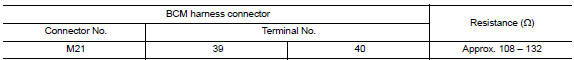
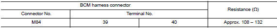
- Check the resistance between the BCM harness connector terminals.
- Without intelligent key system
- With Intelligent Key system
Is the measurement value within the specification? Yes >> go to 3.
No >> repair the bcm branch line.
3.Check power supply and ground circuit
Check the power supply and the ground circuit of the bcm. Refer to the following.
- With intelligent key system: refer to bcs-67, "diagnosis procedure".
- Without intelligent key system: refer to bcs-120, "diagnosis procedure".
Is the inspection result normal? Yes (present error)>>replace the bcm. Refer to the following.
- With intelligent key system: refer to bcs-73, "removal and installation".
- Without Intelligent Key system: Refer to BCS-126, "Removal and Installation".
Yes (past error)>>error was detected in the bcm branch line.
No >> repair the power supply and the ground circuit.
 AV branch line circuit
Diagnosis procedure
1.Check connector
Turn the ignition switch off
Disconnect the battery cable from the negative terminal.
Check the terminals and connectors of the av control unit for damag ...
 Can communication circuit
Diagnosis procedure
1.Connector inspection
Turn the ignition switch off.
Disconnect the battery cable from the negative terminal.
Disconnect all the unit connectors on CAN communication syste ...
Other materials:
Nissan Customer care program
NISSAN CARES . . .
Both NISSAN and your NISSAN dealer are dedicated to serving all your
automotive needs. Your satisfaction with your vehicle and your NISSAN dealer are
our primary concerns. Your NISSAN dealer is always available to assist you with
all your automobile sales and service needs.
...
Seat belt extenders
If, because of body size or driving position, it is
not possible to properly fit the lap/shoulder belt
and fasten it, an extender that is compatible with
the installed seat belts is available that can be
purchased. The extender adds approximately 8 in
(200 mm) of length and may be used for eith ...
AIR Breather hose
Exploded View
Harness bracket
Clip
Air breather hose
Vehicle front
Always replace after every
disassembly.
Removal and Installation
REMOVAL
Remove clips from harness bracket
Remove air breather hose from transaxle assembly.
INSTALLATION
Installation is in the revers ...
