Nissan Sentra B18 (2020-2025) Service Manual: Basic Inspection
Diagnosis and Repair Workflow
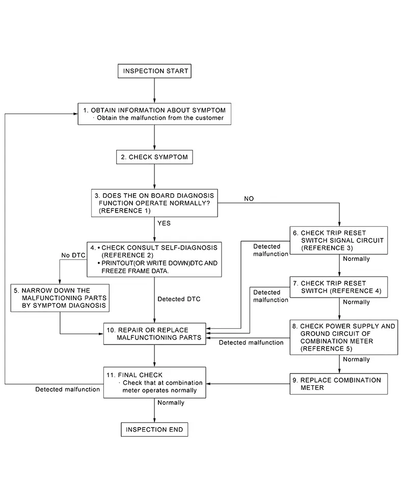
Work Flow
Work flow
OVERALL SEQUENCE
-
Reference 1: On Board Diagnosis Function.
-
Reference 2: DTC Index.
-
Reference 3: Diagnosis Procedure.
-
Reference 4: Component Inspection.
-
Reference 5: Diagnosis Procedure.
DETAILED FLOW
-
OBTAIN INFORMATION ABOUT SYMPTOM
-
Interview the customer to obtain as much information as possible about the conditions and environment under which the malfunction occurred.
GO TO 2.
-
-
CHECK SYMPTOM
-
-
Check the symptom based on the information obtained from the customer.
-
Check that any other malfunctions are present.
-
GO TO 3.
-
-
CHECK ON BOARD DIAGNOSIS OPERATION
-
Check that the on board diagnosis function operates. Refer to On Board Diagnosis Function.
Does the on board diagnosis function operate normally?
YES >>GO TO 4.
NO >>GO TO 6.
-
-
CHECK CONSULT SELF DIAGNOSTIC RESULT
-
 CONSULT
-
Select ÔÇťSelf Diagnostic ResultÔÇŁ mode of ÔÇťMETER/M&AÔÇŁ. Refer to DTC Index.
-
When DTC is detected, follow the instructions below:
-
Record DTC and Freeze Frame Data.
-
-
Is the inspection result normal?
YES >>GO TO 5.
NO >>GO TO 10.
-
-
NARROW DOWN THE MALFUNCTIONING PARTS BY SYMPTOM DIAGNOSIS
-
Perform symptom diagnosis and narrow down the malfunctioning parts.
GO TO 10.
-
-
CHECK TRIP RESET SWITCH SIGNAL CIRCUIT
-
Check trip reset switch signal circuit. Refer to Diagnosis Procedure.
Is inspection result normal?
YES >>GO TO 7.
NO >>GO TO 10.
-
-
CHECK TRIP RESET SWITCH
-
Check trip reset switch. Refer to Component Inspection.
Is inspection result normal?
YES >>GO TO 8.
NO >>GO TO 10.
-
-
CHECK COMBINATION METER POWER SUPPLY AND GROUND CIRCUITS
-
Check combination meter power supply and ground circuits. Refer to Diagnosis Procedure.
Is inspection result normal?
YES >>GO TO 9.
NO >>GO TO 10.
-
-
REPLACE COMBINATION METER
-
Replace combination meter. Refer to Removal and Installation.
GO TO 11.
-
-
REPAIR OR REPLACE MALFUNCTIONING PARTS
-
Repair or replace the malfunctioning parts.
Note:
If DTC is displayed, erase DTC after repair or replace malfunctioning parts.
GO TO 11.
-
-
FINAL CHECK
-
Check that the combination meter operates normally.
Does it operate normally?
YES >>Inspection End
NO >>GO TO 1.
-
Additional Service When Replacing Combination Meter
Work Procedure
Work Procedure
When replacing the combination meter, perform the following procedure before and after replacement.
-
BEFORE REPLACEMENT
-
CONSULT
- Note the odometer mileage of the combination meter.
-
Select ÔÇťSelf Diagnostic ResultÔÇŁ mode of ÔÇťABSÔÇŁ.
Is DTC detected?
YES >>Refer to DTC Index.
NO >>GO TO 2.
-
-
COMBINATION METER CONFIGURATION
-
CONSULT
Perform the combination meter configuration. Refer to Work Procedure.
GO TO 3.
-
-
PERFORM SELF DIAGNOSTIC RESULT
-
CONSULT
Select ÔÇťSelf Diagnostic ResultÔÇŁ mode of ÔÇťMETER/M&AÔÇŁ.
Is DTC detected?
YES>>Refer to DTC Index.
NO>>GO TO 4.
-
-
ROAD TEST (AFTER REPLACEMENT)
-
-
Drive the Nissan Sentra vehicle 1 km (0.62 mi) or more.
-
Check that the odometer shows more mileage than the mileage noted before replacement.
The odometer mileage of the combination meter is also stored and memorized in the ABS actuator and electric unit (control unit). When driving 1 km (0.62 mi) or more after replacing the combination meter, the memorized mileage in the ABS actuator and electric unit (control unit) is written into the new combination meter.
-
Work End.
-
Configuration (combination Meter)
Work Procedure
Work Procedure
-
Since vehicle specifications are not included in the combination meter after replacement, it is required to write Nissan Sentra vehicle specifications with CONSULT.
-
Configuration has three functions as follows.
Function
Description
Read/Write Configuration
Before Replace ECU
Allows the reading of Nissan Sentra vehicle specification written in combination meter to store the specification in CONSULT.
After Replace ECU
Allows the writing of the Nissan Sentra vehicle information stored in CONSULT into the combination meter.
Manual Configuration
Allows the writing of the Nissan Sentra vehicle specification into the combination meter by hand.
|
Parts name |
Work |
Additional service |
Remarks |
||
|---|---|---|---|---|---|
|
Replacement |
Removal |
||||
|
combination meter |
├Ś |
ÔÇö |
Configuration |
The combination meter do not operate normally unless the additional services are performed. |
|
CAUTION:
-
Use ÔÇťManual ConfigurationÔÇŁ only when ÔÇťParts numberÔÇŁ of combination meter cannot be read.
-
If an error occurs during configuration, start over from the beginning.
-
CHECKING PARTS NUMBER
-
CONSULT
-
Select ÔÇťBefore Replace ECUÔÇŁ of ÔÇťRead/Write ConfigurationÔÇŁ.
-
Check that ÔÇťParts numberÔÇŁ is displayed.
-
Is ÔÇťParts numberÔÇŁ displayed?
YES >>GO TO 2.
NO >>GO TO 6.
-
-
VERIFYING PARTS NUMBER (1)
-
CONSULT
Compare a ÔÇťParts numberÔÇŁ displayed on the CONSULT screen with the one searched by using FAST (service parts catalogue) to check that these ÔÇťParts numberÔÇŁ agree with each other.
Note:
For the ÔÇťParts numberÔÇŁ searched by using FAST (service parts catalog), use the last five digits of the ÔÇťParts numberÔÇŁ.
GO TO 3.
-
-
SAVING PARTS NUMBER
-
CONSULT
Save ÔÇťParts numberÔÇŁ.
GO TO 4.
-
-
REPLACE COMBINATION METER (1)
-
Replace combination meter. Refer to Removal and Installation.
GO TO 5.
-
-
WRITING (AUTOMATIC WRITING)
-
CONSULT
-
Select ÔÇťAfter Replace ECUÔÇŁ of ÔÇťRe/programming, ConfigurationÔÇŁ or that of ÔÇťRead / Write ConfigurationÔÇŁ.
-
Select the ÔÇťParts numberÔÇŁ agreeing with the one stored on CONSULT and the one searched by using FAST (service parts catalogue) to write the ÔÇťParts numberÔÇŁ into the combination meter.
-
GO TO 8.
-
-
REPLACE COMBINATION METER (2)
-
Replace combination meter. Refer to Removal and Installation.
GO TO 7.
-
-
WRITING (MANUAL WRITING)
-
CONSULT
-
Select ÔÇťManual ConfigurationÔÇŁ.
-
Select the ÔÇťParts numberÔÇŁ searched by using FAST (service parts catalogue) to write the ÔÇťParts numberÔÇŁ into the combination meter.
Note:
For the ÔÇťParts numberÔÇŁ searched by using FAST (service parts catalog), use the last five digits of the ÔÇťParts numberÔÇŁ.
-
GO TO 8.
-
-
VERIFYING PARTS NUMBER (2)
-
CONSULT
Compare a ÔÇťParts numberÔÇŁ displayed on the CONSULT screen with the one searched by using FAST (service parts catalogue) to check that these ÔÇťParts numberÔÇŁ agree with each other.
Note:
For the ÔÇťParts numberÔÇŁ searched by using FAST (service parts catalog), use the last five digits of the ÔÇťParts numberÔÇŁ.
GO TO 9.
-
-
OPERATION CHECK
-
Confirm that each function controlled by combination meter operates normally.
Work End.
-
Other materials:
Air Breather Hose
Exploded View
Exploded View
1.
Air breather hose
2.
Transaxle assembly
A.
...
C1741-21 Tire Pressure Sensor No Data Fl
Dtc Description
DTC Description
Note:
The Signal Tech II Tool [ÔÇô (NI-50190)] can be used
to perform the following functions: Refer to the Signal Tech II User
Guide for additional information.
Activate and display TPMS sensor IDs
Display tire pressure rep ...
Instrument Panel. Precaution. Precautions
Precautions
Precaution for Supplemental Restraint System (srs) "air Bag" and "seat Belt Pre-Tensioner"
Precaution for Supplemental Restraint System (SRS) "AIR BAG" and "SEAT BELT PRE-TENSIONER"
The Supplemental Restraint System such as
ÔÇťAIR BAGÔÇŁ and ÔÇťSEAT BELT PRE-T ...