Nissan Sentra B18 (2020-2025) Service Manual: B1339 Rear Camera Connection
Dtc Description
DTC Description
DTC DETECTION LOGIC
|
DTC No. |
CONSULT screen terms (Trouble diagnosis content) |
DTC detection condition |
||
|---|---|---|---|---|
|
B1339-8F |
Rear camera connection (Rear view camera connection) |
[–] |
Diagnosis condition |
When ignition switch is ON. |
|
Signal (terminal) |
Camera image signal circuit (terminal 40) |
|||
|
Threshold |
– |
|||
|
Diagnosis delay time |
30 seconds or more |
|||
POSSIBLE CAUSE
-
Camera image signal circuit
-
Rear view camera
-
AV control unit
FAIL-SAFE
Rear view camera is inoperative.
Confirmation Procedure
Confirmation Procedure
-
PERFORM DTC CONFIRMATION PROCEDURE
-
 CONSULT
-
Ignition switch ON.
-
Ignition switch OFF and wait at least 30 seconds.
-
Ignition switch ON and wait at least 30 seconds or more.
-
Select “Self Diagnostic Result� mode of “MULTI AV�.
-
Check DTC.
-
Is DTC B1339–8F detected?
YES>>Proceed to DTC Diagnosis Procedure.
NO>>To check malfunction symptom before repair: Refer to Intermittent Incident.
NO>>Confirmation after repair: Inspection End.
-
Dtc Diagnosis Procedure
DTC Diagnosis Procedure
-
CHECK CAMERA IMAGE SIGNAL CIRCUIT FOR OPEN
-
-
Ignition switch OFF.
-
Disconnect AV control unit connector and rear view camera connector.
-
Check the continuity between AV control unit connector and rear view camera connector.
AV control unit
Rear view camera
Continuity
Connector
Terminal
Connector
Terminal
M93
40
B30
3
Yes
-
Is the inspection result normal?
YES >>GO TO 2.
NO >>Repair harness or connector.
-
-
CHECK CAMERA IMAGE SIGNAL CIRCUIT FOR SHORT
-
Check the continuity between AV control unit connector and ground.
AV control unit
−
Continuity
Connector
Terminal
M93
40
Ground
No
Is the inspection result normal?
YES >>GO TO 3.
NO >>Repair harness or connector.
-
-
CHECK CAMERA IMAGE SIGNAL
-
-
Connect AV control unit connector and rear view camera connector.
-
Ignition switch ON.
-
Shift the selector lever to “R� position
-
Check the signal between AV control unit connector and ground.
AV control unit
(-)
Condition
Reference value
(+)
Connector
Terminal
M93
40
Ground
Camera image is displayed
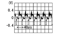
-
Is the inspection result normal?
YES >>Replace AV control unit. Refer to Removal and Installation.
NO >>Replace rear view camera. Refer to Removal and Installation.
-
Other materials:
Wiper & Washer. Service Data and Specifications (sds). Service Data and Specifications (sds). Specifications
Service Data and Specifications (sds). Specifications
Specifications
Specifications
WITH WASHER LEVEL SWITCH
Windshield washer fluid
capacity
4.2
(4 1/2 US qt, 3 3/4 Imp qt)
...
P0139 Ho2s2
Dtc Description
DTC Description
The heated oxygen sensor 2 has a much longer switching time
between rich and lean than the air fuel ratio (A/F) sensor 1. The oxygen storage
capacity of the three way catalyst 1 causes the longer switching time. To judge
the malfunctions of heated oxy ...
B2f06-15 Back Door/trunk Opener Switch
Dtc Description
DTC Description
DTC DETECTION LOGIC
DTC No.
CONSULT screen items (Trouble
diagnosis content)
DTC detecting condition
...