Nissan Sentra Service Manual: Air cleaner and air duct
Exploded View
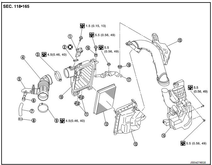
- Mass air flow sensor
- Mass air flow gasket
- Clamp
- Air duct (suction side)
- Resonator
- Clamp
- PCV hose
- Clamp
- Clamp
- Air cleaner cover
- Mounting rubber
- Air cleaner filter
- Air cleaner body
- Air duct inlet (lower)
- Air duct inlet (upper)
- Mounting rubber
- Bracket
- Grommet
Removal and Installation
REMOVAL
NOTE:
Mass air flow sensor is removable under the car-mounted condition.
- Remove engine room cover. Refer to EM-24, "Exploded View".
- Remove air duct inlet (upper).
- Remove air cleaner filter from the air cleaner cover.
- Disconnect mass air flow sensor harness connector, and remove harness clamp from air cleaner body assembly.
- Disconnect PCV hose and transaxle breather hose.
- Remove air cleaner body.
- Remove air duct (suction side).
- Add matching marks if necessary for easier installation.
- Remove air cleaner cover.
- Remove mass air flow sensor from air cleaner cover, if necessary.
CAUTION:
Handle the mass air flow sensor with following cares.
- Do not shock the mass air flow sensor.
- Do not disassemble the mass air flow sensor.
- Do not touch the sensor of the mass air flow sensor.
- Remove air duct inlet (lower) with the following procedure.
- Remove front combination lamp (LH). Refer to EXL-119, "Exploded View".
- Remove air duct inlet (lower).
INSTALLATION
CAUTION:
Do not reuse O-rings.
Installation is in the reverse order of removal.
- Align marks. Attach each joint. Screw clamps firmly.
- Tabs shall be fixed after inserting air cleaner body assembly protrusion to air cleaner case notch hole.
- Make sure whether air cleaner body has been firmly installed by shaking it.
Inspection
INSPECTION AFTER REMOVAL
Inspect air duct (suction side), air duct inlet (upper), air duct inlet (lower) and resonator for crack or tear.
- If anything is found, replace air duct (suction side), air duct inlet (upper), air duct inlet (lower) and resonator.
 Engine room cover
Exploded View
Engine room cover
Mounting rubber (Black)
Mounting rubber (Gray)
Removal and Installation
REMOVAL
CAUTION:
Do not damage or scratch engine room cover when installing o ...
 Intake manifold
Exploded View
Clamp
PCV hose
Bracket
Intake manifold gasket
Intake manifold
Mount rubber
Clamp
EVAP hose
EVAP canister purge volume
control solenoid valve
Electric throttl ...
Other materials:
Instrument lower panel lH
Removal and Installation
REMOVAL
Remove the instrument side finisher LH (1) using a suitable tool.
Remove the hood and fuel filler handle assembly from the instrument
lower panel LH. Refer to DLK-191,
"FUEL FILLER OPENER CABLE : Removal and Installation".
Release the ...
Operating tips
When the engine coolant temperature and
outside air temperature are low, the air flow
from the foot outlets may not operate for a
maximum of 150 seconds. However, this is
not a malfunction. After the coolant temperature
warms up, air flow from the foot outlets
will operate normally.
...
Av branch line circuit
Diagnosis Procedure
1.Check connector
Turn the ignition switch off.
Disconnect the battery cable from the negative terminal.
Check the terminals and connectors of the av control unit for damage,
bend and loose connection (unit
side and connector side).
Is the inspection result norma ...
