Nissan Sentra Service Manual: Abs branch line circuit
Diagnosis procedure
1.Check connector
- Turn the ignition switch OFF.
- Disconnect the battery cable from the negative terminal.
- Check the terminals and connectors of the abs actuator and electric unit (control unit) for damage, bend and loose connection (unit side and connector side).
Is the inspection result normal? Yes >> go to 2.
No >> repair the terminal and connector.
2.Check harness for open circuit
- Disconnect the connector of abs actuator and electric unit (control unit).
- Check the resistance between the abs actuator and electric unit (control unit) harness connector terminals.
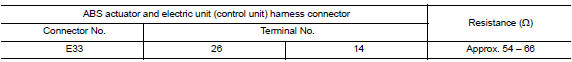
Is the measurement value within the specification? Yes >> go to 3.
No >> repair the abs actuator and electric unit (control unit) branch line.
3.Check power supply and ground circuit
Check the power supply and the ground circuit of the abs actuator and electric unit (control unit). Refer to brc-62, "diagnosis procedure".
Is the inspection result normal? Yes (present error)>>replace the abs actuator and electric unit (control unit). Refer to brc-110, "removal and installation".
Yes (past error)>>error was detected in the abs actuator and electric unit (control unit) branch line.
No >> repair the power supply and the ground circuit.
 Ecm branch line circuit
Diagnosis procedure
1.Check connector
Turn the ignition switch off.
Disconnect the battery cable from the negative terminal.
Check the terminals and connectors of the ecm for damage, bend and ...
 Ipdm-e branch line circuit
Diagnosis procedure
1.Check connector
Turn the ignition switch OFF.
Disconnect the battery cable from the negative terminal.
Check the terminals and connectors of the IPDM E/R for damage, ben ...
Other materials:
Warning signals
To help prevent the vehicle from moving unexpectedly
by erroneous operation of the Intelligent
Key or to help prevent the vehicle from being
stolen, a chime or buzzer sounds from inside and
outside the vehicle and a warning light comes on
in the instrument panel.
When a chime or beep sounds ...
System description
Component parts
Component parts location
Front tweeter lh (if equipped)
Steering switches
Audio unit
Front tweeter rh (if equipped)
Microphone (if equipped)
Front door speaker lh
Front door speaker RH
Rear speaker rh
Rear speaker lh
Antenna amp.
Window antenna
Bluetoot ...
Brake booster
Inspection
Operation
Depress the brake pedal several times at five second intervals with
the engine stopped. Start the engine with the brake pedal fully
depressed. Check that the clearance between brake pedal and dash
lower panel decreases.
NOTE:
A slight impact with a small click may be felt ...
