Nissan Sentra Service Manual: Trunk lid
Trunk lid assembly
Trunk lid assembly : exploded view
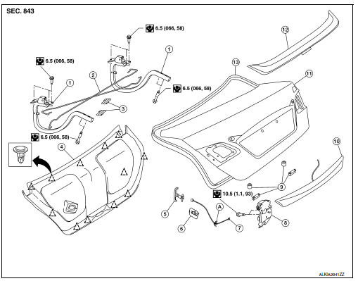
- Trunk lid hinge LH/RH
- Torsion bar LH/RH
- Torsion bar clips
- Trunk lid finisher (if equipped)
- Emergency release handle
- Emergency release handle clip
- Emergency release handle cable
- Trunk lid lock
- Trunk lid bumpers
- License lamp finisher
- Trunk lid
- Rear spoiler (if equipped)
- Weatherstrip
- Clip
 Clip
Clip
Trunk lid assembly : removal and installation
CAUTION:
- Use two people when removing or installing trunk lid assembly due to its heavy weight.
- Use protective tape or shop cloths to protect surrounding components from damage during removal and installation of trunk lid assembly.
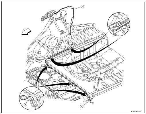
REMOVAL
- Remove trunk lid finisher (if equipped). Refer to INT-45, "Removal and Installation".
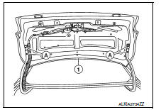
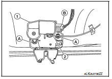
- Disconnect the harness connectors in the trunk lid assembly (1) and remove the harness clips (A) then pull out harness from the trunk lid assembly (1).
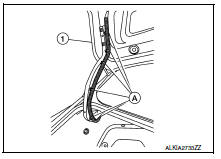
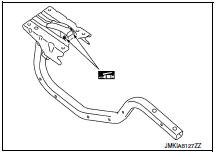
- Remove the bolts (A) and remove the trunk lid assembly (1).
INSTALLATION
Installation is in the reverse order of removal.
CAUTION:
After installation, perform the trunk lid assembly adjustment procedure. Refer to DLK-185, "TRUNK LID ASSEMBLY : Adjustment".
Trunk lid assembly : adjustment
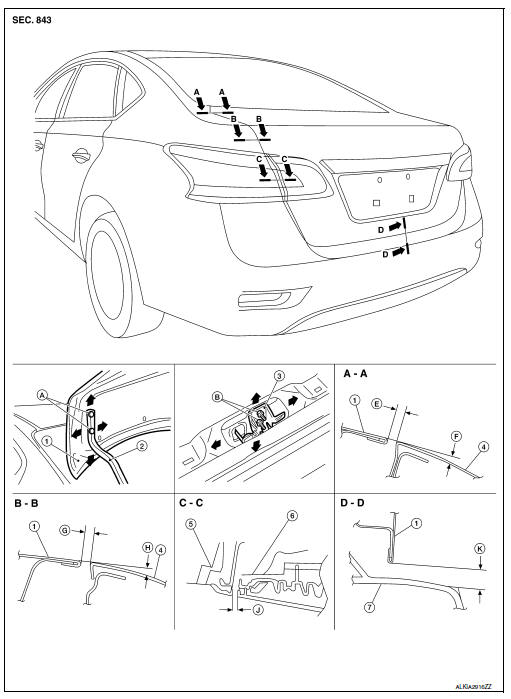
- Trunk lid assembly
- Trunk lid hinge
- Trunk lid striker
- Body side outer
- Rear combination lamp
- Reflector
- Rear bumper fascia
- Trunk lid bolts
- Striker bolts
Check the clearance and the surface height between trunk lid and each part by visual inspection and tactile feel.
If the clearance and the surface height are out of specification, adjust them according to the adjustment procedures.
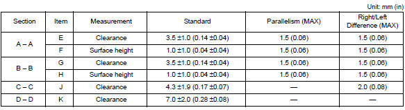
LONGITUDINAL CLEARANCE
Trunk Lid Removed From Hinge
- Loosen the trunk lid to hinge bolts.
- Move the trunk lid so that the clearance measurements are within specifications provided.
- Tighten the trunk lid to hinge bolts.
Trunk Lid Hinge Removed From Vehicle
- Remove the rear parcel shelf finisher. Refer to INT-33, "Removal and Installation".
- Loosen the hinge to parcel shelf bolts.
- Move the trunk lid so that the clearance measurements are within specifications provided.
- Tighten the hinge to parcel shelf bolts
- Install the rear parcel shelf finisher. Refer to INT-33, "Removal and Installation".
SURFACE HEIGHT ADJUSTMENT
- Loosen the bumper rubber.
- Loosen the striker bolts.
- Lift up the trunk lid approx. 100 - 150 mm (3.94 - 5.91 in) height then close it lightly. Make sure it engages firmly with the trunk lid closed.
- Tighten the trunk lid striker.
Trunk lid hinge
Trunk lid hinge : removal and installation
REMOVAL
- Remove trunk lid assembly. Refer to DLK-183, "TRUNK LID ASSEMBLY : Removal and Installation".
- Remove torsion bar. Refer to DLK-187, "TORSION BAR : Removal and Installation".
- Remove rear parcel shelf finisher. Refer to INT-33, "Removal and Installation".
- Remove trunk lid hinge bolts (body side) and remove.
INSTALLATION
Installation is in the reverse order of removal.
CAUTION:
- Check trunk lid open/close, lock/unlock operation after installation.
- After installation, perform the trunk lid assembly adjustment procedure. Refer to DLK-185, "TRUNK LID ASSEMBLY : Adjustment".
Check trunk lid hinge rotating point for poor lubrication. If necessary, apply a suitable multi-purpose grease.
Torsion bar
Torsion bar : removal and installation
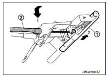
REMOVAL
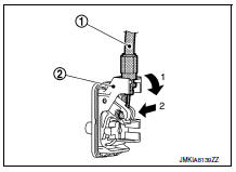
- Remove torsion bar clips.
- Support the trunk lid assembly using a suitable tool.
WARNING:
Bodily injury may occur if hood assembly is not supported properly when removing hood assembly.
- Lift torsion bar (1) using a suitable tool (A) as shown to remove
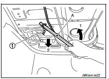
NOTE:
The suitable tool specifications are as shown.
INSTALLATION
Installation is in the reverse order of removal.
CAUTION:
After installation check the trunk lid open/close, lock/unlock operation.
Trunk lid lock
Trunk lid lock : removal and installation
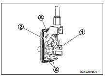
REMOVAL
- Remove the trunk lid finisher (if equipped). Refer to INT-45, "Removal and Installation".
- Disconnect the harness connector (B) and emergency release handle (2) from the trunk lid lock (1).
- Remove the trunk lid lock bolts (A) and remove.
INSTALLATION
Installation is in the reverse order of removal.
CAUTION:
After installation, perform the trunk lid assembly adjustment procedure. Refer to DLK-185, "TRUNK LID ASSEMBLY : Adjustment".
Emergency lever
EMERGENCY LEVER : Removal and Installation
REMOVAL
- Remove the trunk lid finisher (if equipped). Refer to INT-45, "Removal and Installation".
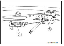
- Using a suitable tool release the pawls and remove emergency release handle (1) from trunk lid assembly.
 : Pawl
- Disconnect emergency release handle cable (2) from trunk lid lock assembly (3).
INSTALLATION
Installation is in the reverse order of removal.
Trunk lid striker
TRUNK LID STRIKER : Removal and Installation
REMOVAL
- Remove the trunk kicking plate. Refer to INT-42, "TRUNK REAR PLATE : Removal and Installation".
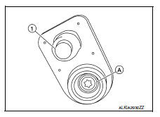
- Remove bolts (A) and striker (1).
INSTALLATION
Installation is in the reverse order of removal.
CAUTION:
After installation, perform the trunk lid assembly adjustment procedure. Refer to DLK-185, "TRUNK LID ASSEMBLY : Adjustment".
Fuel filler lid opener
Exploded view
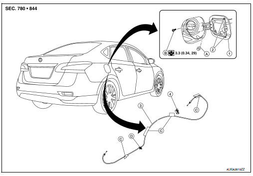
- Fuel filler lid
- Bumper rubber
- Fuel filler lid opener cable
- Fuel filler lid lock
- Clip
- Bolt
- Cable protector
Fuel filler lid
Fuel filler lid : removal and installation
REMOVAL
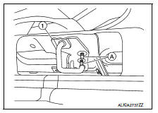
- Fully open fuel filler lid.
- Remove fuel cap clip (A).
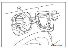
- Remove fuel filler lid screws (A) and fuel filler lid (1).
INSTALLATION
Installation is in the reverse order of removal.
CAUTION:
After installation, check fuel filler lid assembly open/close, lock/unlock operation.
NOTE:
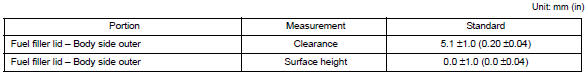
- The following table shows the specifications for a correctly installed fuel filler lid.
- Fitting adjustment cannot be performed.
Fuel filler opener cable
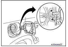
FUEL FILLER OPENER CABLE : Removal and Installation
REMOVAL
- Remove hood and fuel filler handle assembly bolts (A).
- Release fuel filler lid opener cable (2) by pulling downward and then sliding cable end to the side to remove from hood and fuel filler handle assembly (1).
- Remove dash side finisher (LH). Refer to IP-14, "Removal and Installation".
- Remove center pillar lower finisher (LH). Refer to INT-27, "CENTER PILLAR LOWER FINISHER : Removal and Installation".
- Remove rear seat bolster (LH). Refer to SE-24, "Removal and Installation - Rear Seat Bolster".
- Remove trunk side finisher (LH). Refer to INT-43, "TRUNK SIDE FINISHER : Removal and Installation".
- Remove fuel filler lid opener cable (1) from fuel filler lid lock assembly. Refer to DLK-192, "FUEL FILLER LID LOCK : Removal and Installation".
 Front
Front
- Remove each cable protector (A), then remove fuel filler lid opener cable (1).
INSTALLATION
Installation is in the reverse order of removal.
CAUTION:
After installation, check fuel filler lid assembly open/close, lock/unlock operation.
Fuel filler lid lock
Fuel filler lid lock : removal and installation
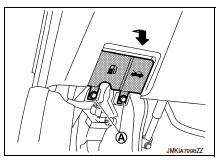
REMOVAL
- Fully open fuel filler lid.
- Insert a suitable tool (A) as shown into bottom of fuel filler lock assembly(1).
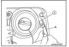
- Release upper and lower pawls (A) using a suitable tool and remove fuel filler lid lock assembly (1).
CAUTION:
Be careful not to damage gasket (2) when removing.
- Disconnect fuel filler lid opener cable (1) by pulling downward and then sliding cable end to the side to remove from fuel filler lid lock assembly (2).
INSTALLATION
Installation is in the reverse order of removal.
CAUTION:
After installation, check fuel filler lid assembly open/close, lock/unlock operation.
Door switch
Removal and installation
REMOVAL
- Remove the door switch screw (A).
- Disconnect the harness connector from the door switch (1) and remove.
INSTALLATION
Installation is in the reverse order of removal.
 Door handle
Front door handle
Front door handle : exploded view
Outside handle bracket
Front gasket
Outside handle
Intelligent key button
Door key cylinder rod
Inside handle assembly
Rear ga ...
 Inside key antenna
Console
CONSOLE : Removal and Installation
REMOVAL
Remove the shift selector finisher. Refer to IP-17, "Removal and
Installation".
Remove the inside key antenna (console) screws (A ...
Other materials:
P0500 VSS
EXCEPT FOR M/T MODELS
EXCEPT FOR M/T MODELS : Description
ECM receives vehicle speed signals from two different paths via CAN
communication line: One is from the
ABS actuator and electric unit (control unit) via the combination unit and the
other is from TCM.
EXCEPT FOR M/T MODELS : DTC Logi ...
Heating and cooling unit assembly
Exploded view
With air conditioning
Defroster seal
Center ventilator seal
Upper distribution module
Side ventilator seal (LH)
Blower motor
Blower unit
Intake door motor
Power transistor
Power transistor wiring harness
Front floor duct (lh)
Vent and defroster linkage
Mo ...
Rear combination lamp
Exploded view
Rear combination lamp
Rear turn signal lamp bulb
Rear turn signal lamp socket
LED lamp harness connector
Rear combination lamp harness
connector
Back-up lamp bulb socket
Back-up lamp bulb
Removal and installation
Removal
Partially remove trunk side finis ...
